Bounded area rapid global positioning method based on laser radar
A laser radar and bounded area technology, applied in the direction of electromagnetic wave re-radiation, measuring devices, instruments, etc., can solve problems such as being easily affected by ambient light, low positioning accuracy, and complex algorithms
- Summary
- Abstract
- Description
- Claims
- Application Information
AI Technical Summary
Problems solved by technology
Method used
Image
Examples
Embodiment 1
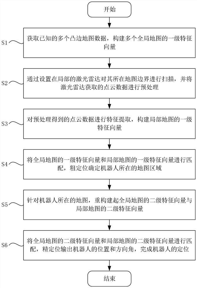
[0054] Such as figure 1 As shown, a fast global positioning method for a lidar bounded area includes the following steps:
[0055] S1: Obtain multiple known convex-edge map data, and construct first-level feature vectors of multiple global maps;
[0056] S2: Scan the boundary of the map with the local lidar, and preprocess the point cloud data obtained by the lidar;
[0057] S3: Perform feature extraction on the preprocessed point cloud data, and construct a first-level feature vector of the local map;
[0058] S4: Match the first-level feature vectors of the global map with the first-level feature vectors of the local map, and roughly locate the map area where the robot is located;
[0059] S5: For the map where the robot is located, reconstruct the secondary feature vector of the global map and the secondary feature vector of the local map;
[0060] S6: Match the secondary eigenvectors of the global map with the secondary eigenvectors of the local map, and output the pos...
Embodiment 2
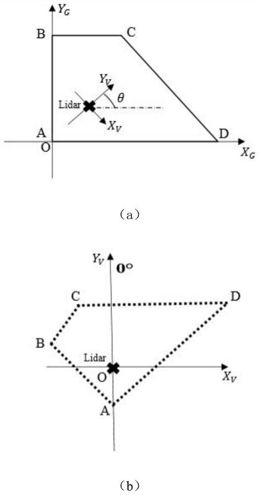
[0063] More specifically, on the basis of Example 1, such as figure 2 As shown, define the conversion relationship between the ground coordinate system and the vehicle coordinate system and the vehicle direction angle as OX G Y G Ground coordinate system, OX V Y V is the vehicle coordinate system. The 0° orientation of the laser radar is defined as the positive direction of the vertical axis of the vehicle coordinate system, and the vehicle direction angle is defined as the angle between the 0° direction of the laser radar and the positive direction of the horizontal axis of the ground coordinate system. The maps in the embodiments are all four-sided convex polygon maps.
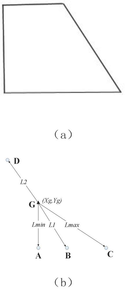
[0064] More specifically, the step S1 is as follows: first perform feature extraction on a plurality of known maps (i.e. global maps) in the ground coordinate system, and substitute the coordinates of k=4 vertices of the convex polygonal map into the barycenter coordinate calculation formula:
[0065] ...
PUM
 Abstract
Description
Claims
Application Information
 - R&D
- Intellectual Property
- Life Sciences
- Materials
- Tech Scout
- Unparalleled Data Quality
- Higher Quality Content
- 60% Fewer Hallucinations
Browse by: Latest US Patents, China's latest patents, Technical Efficacy Thesaurus, Application Domain, Technology Topic, Popular Technical Reports.
© 2025 PatSnap. All rights reserved.Legal|Privacy policy|Modern Slavery Act Transparency Statement|Sitemap|About US| Contact US: help@patsnap.com


