Optical waveguide and near-to-eye display system

An optical waveguide and waveguide technology, applied in the field of optics, can solve the problems of poor energy utilization rate and incomplete coupling of image beams, and achieve the effect of improving energy utilization rate

Pending Publication Date: 2020-09-18
SHENZHEN LOCHN OPTICS TECH CO LTD
View PDF5 Cites 10 Cited by
  • Summary
  • Abstract
  • Description
  • Claims
  • Application Information

AI Technical Summary

Problems solved by technology

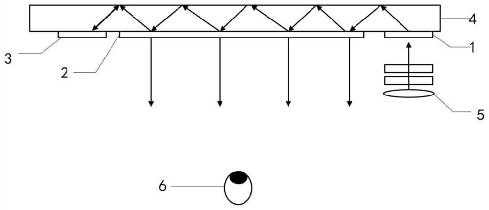
However, when the image beam propagates to the edge of the outcoupling grating area, because there is no outcoupling grating, part of the image beam is not completely outcoupled, and the energy utilization rate is not good, so it is very urgent to improve the energy utilization rate of the two-dimensional extended diffractive optical waveguide.

Method used


Image

  • Optical waveguide and near-to-eye display system
  • Optical waveguide and near-to-eye display system
  • Optical waveguide and near-to-eye display system

Examples


Embodiment Construction

[0028] The present invention will be described in detail below in conjunction with specific embodiments. The following examples will help those skilled in the art to further understand the present invention, but do not limit the present invention in any form. It should be noted that those skilled in the art can make several modifications and improvements without departing from the concept of the present invention. These all belong to the protection scope of the present invention.

[0029] In order to facilitate the understanding of the present application, the present application will be described in more detail below in conjunction with the accompanying drawings and specific embodiments. Unless otherwise defined, all technical and scientific terms used in this specification have the same meaning as commonly understood by one of ordinary skill in the technical field of this application. The terms used in the description of the present application are only for the purpose of ...


PUM


Abstract

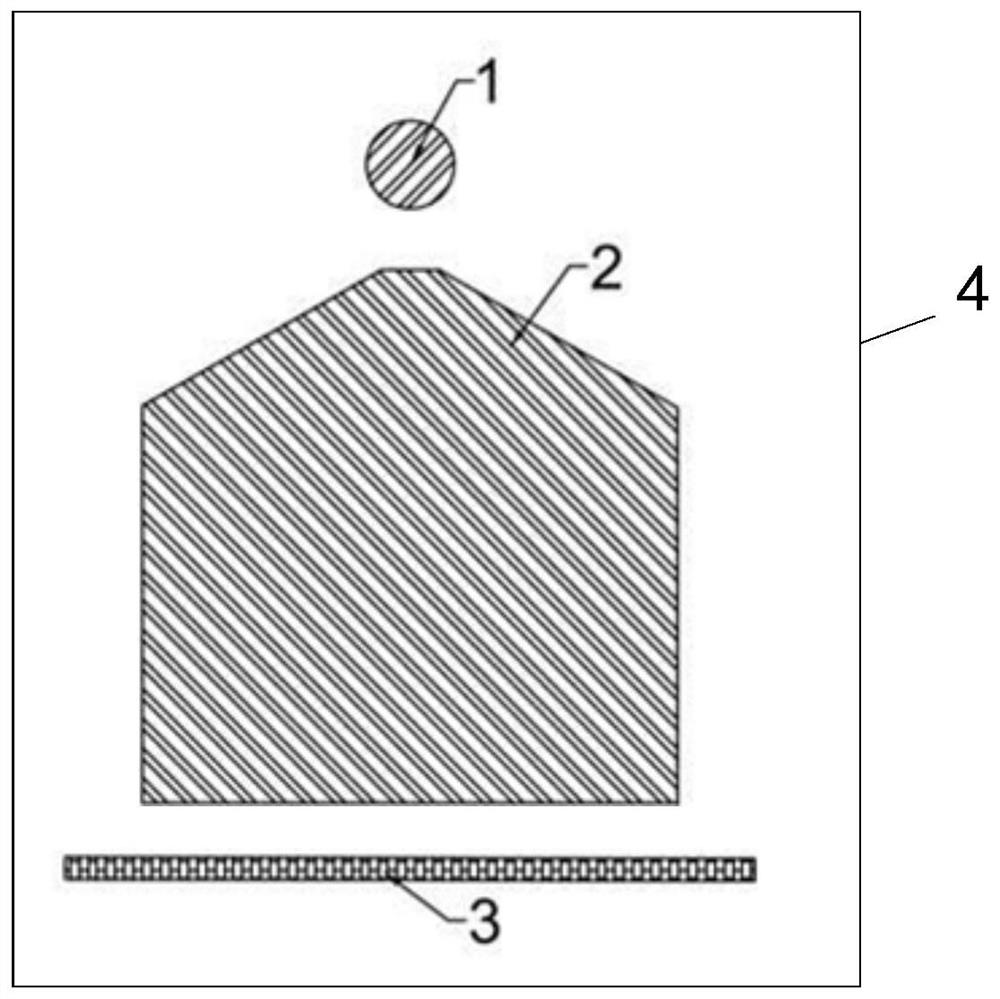
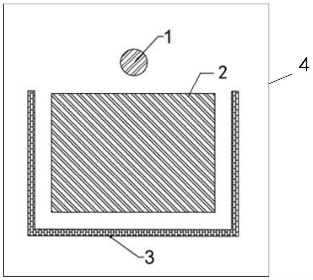
The embodiment of the invention relates to the technical field of optics, and in particular relates to an optical waveguide and a near-to-eye display system. The optical waveguide provided by the embodiment of the invention comprises a waveguide substrate, a coupling-in region, a coupling-out region and a light return region; the coupling-in region, the coupling-out region and the light return region are arranged on the waveguide substrate; the coupling-in region is used for coupling in a light beam with image information; the coupling-out region is used for coupling out the light beam with the image information; the light return region is used for reversely returning the light beam with the image information to the coupling-out region; the coupling-out region comprises at least three sideedges; at least one side edge of the coupling-out region is provided with the light return region; when an image light beam is propagated to the edge of the coupling-out region, part of the image light beam can be reversely propagated back to the coupling-out region due to the action of the light return region and then is coupled out to human eyes through the coupling-out region, and therefore the energy utilization rate of the two-dimensional expansion diffraction optical waveguide is increased.

Description

technical field [0001] The embodiments of the present invention relate to the field of optical technology, and in particular to an optical waveguide and a near-eye display system. Background technique [0002] Currently, in AR (Augmented Reality, augmented reality technology) devices, the relief grating waveguide technology has received extensive attention. Due to the convenience of nanoimprinting, and the advantages of large field of view and large eye movement range compared with other waveguide solutions, the relief grating waveguide scheme has been widely studied. [0003] The existing embossed grating waveguide schemes mainly include waveguide schemes based on one-dimensional gratings and waveguide schemes based on two-dimensional gratings. The grating, the image light beam emitted by the image light source is coupled into the optical waveguide substrate through the coupling grating, and propagates in the optical waveguide substrate in a way of total reflection. users...

Claims


Application Information

Patent Timeline
Patent Type & Authority Applications(China)
IPC IPC(8): G02B6/00G02B5/18G02B27/01
CPCG02B6/00G02B5/1842G02B5/1814G02B5/1819G02B27/0101
Inventor 宋强郭晓明黄浩马国斌
Owner SHENZHEN LOCHN OPTICS TECH CO LTD
Why Eureka
Try Eureka