
Laser map region segmentation method

A region segmentation and map technology, which is applied in the field of laser vision to build grid maps, can solve the problems of robot work efficiency reduction, achieve effective segmentation and improve work efficiency

Pending Publication Date: 2020-09-18
AMICRO SEMICON CORP
View PDF1 Cites 4 Cited by
  • Summary
  • Abstract
  • Description
  • Claims
  • Application Information

AI Technical Summary

Problems solved by technology

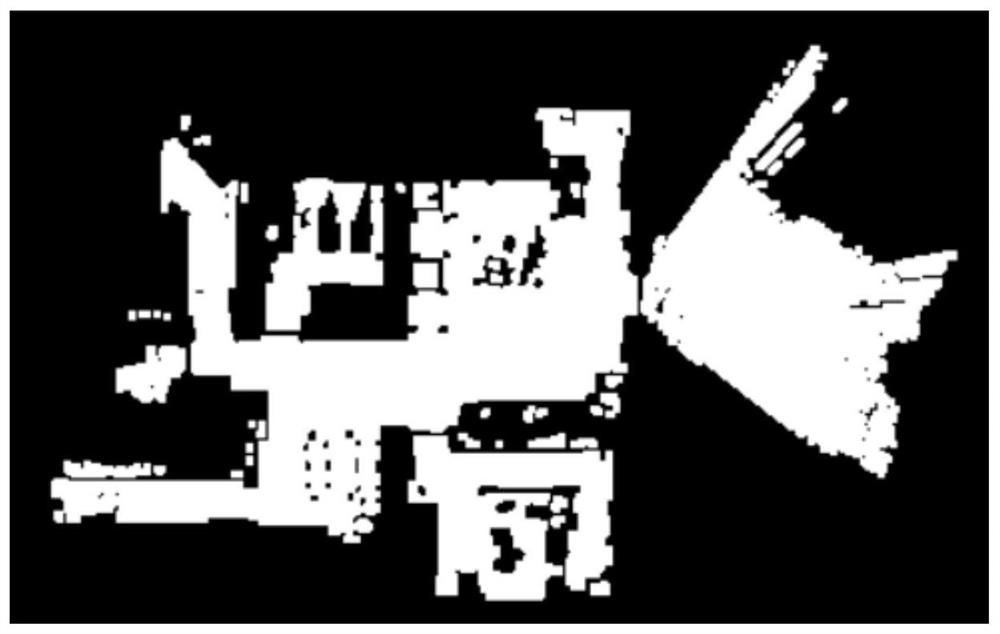
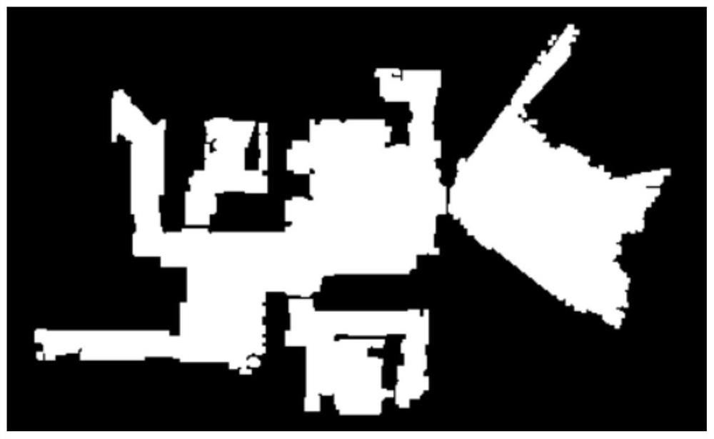
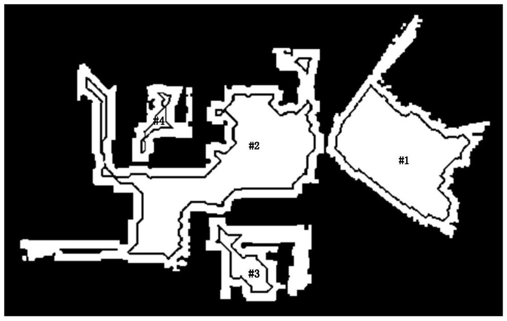
[0003] In order to solve the above technical problems, the present invention proposes a laser map region segmentation method, which uses the contour boundary line scanned by laser data to be closer to the wall, and then determines the center of the robot working area in the region to be divided according to the contour boundary line scanned by laser data Points, and on this basis, use the watershed algorithm to iteratively segment the laser map, so as to determine which pixel areas belong to the same working area, realize the segmentation of the working area, and reduce the possibility that the entire free area may be divided into multiple areas. The problem of reduced work efficiency

Method used


Image

  • Laser map region segmentation method
  • Laser map region segmentation method
  • Laser map region segmentation method

Examples


Embodiment Construction

[0016] The technical solutions in the embodiments of the present invention will be described in detail below with reference to the drawings in the embodiments of the present invention. To further illustrate the various embodiments, the present invention is provided with accompanying drawings. These drawings are a part of the disclosure of the present invention, which are mainly used to illustrate the embodiments, and can be combined with related descriptions in the specification to explain the operating principles of the embodiments. With reference to these contents, those skilled in the art should understand other possible implementations and advantages of the present invention. Components in the figures are not drawn to scale, and similar component symbols are generally used to denote similar components.

[0017] The embodiment of the present invention discloses a region segmentation method of laser map, such as Figure 5 shown, including:

[0018] Step S1. By setting the...


PUM


Abstract

The invention discloses a laser map area segmentation method comprising the following steps: 1, denoising a grayed laser map, wherein the laser map is a map pre-constructed through rotary scanning ofa laser sensor assembled on a robot, and the laser map comprises map environment contour information obtained through laser scanning; step 2, according to distance information between a white pixel point of the grayed laser map and a black pixel point marked by a nearest obstacle, obtaining a laser map, determining central points of at least two robot working areas, secondly, segmenting the imageof the laser map processed in the first step into closed map areas with the center point of the robot working area as a local minimum value point and meeting the requirement for the optimal working area of the robot through a watershed algorithm, wherein each closed map area is an influence area obtained through outward expansion of the center point of the corresponding robot working area. Therefore, the situation that the working efficiency of the robot is reduced after the map is divided into multiple areas is avoided.

Description

technical field [0001] The invention relates to the technical field of laser vision building grid maps, in particular to an area segmentation method for laser maps. Background technique [0002] In the field of robotics, maps are one of the main tools to help robots describe their environment and precisely locate them. The most common type of map used in robotic autonomous localization and navigation techniques is the grid map. However, the existing 4*4 covering cleaning method does not reasonably use the obstacle information in the grid map to divide multiple room areas, so that an autonomous mobile robot's understanding of the environment only stays at the level of independent rooms; The map segmentation method does not effectively use the linear advantage brought by laser sensor scanning, and it is easy to divide the idle area in the grid map into more areas and reduce the working efficiency of the robot. Contents of the invention [0003] In order to solve the above ...

Claims


Application Information

Patent Timeline
IPC IPC(8): G06T7/11G06T5/00G06T7/90
CPCG06T7/11G06T7/90G06T2207/20152G06T2207/10024G06T5/70
Inventor 周和文黄惠保陈卓标
Owner AMICRO SEMICON CORP
Learn More