Eureka AIR delivers breakthrough ideas for toughest innovation challenges, trusted by R&D personnel around the world.

Automatic cap pressing mechanism of fuse

A fuse and automatic technology, applied in fuse manufacturing and other directions, can solve the problems of low production efficiency, irregular coating position, low qualification rate, etc., and achieve the effect of reducing product damage rate, ensuring capping efficiency, and high degree of automation.

Pending Publication Date: 2020-09-18
大连北方真空开关有限公司
View PDF0 Cites 3 Cited by
  • Summary
  • Abstract
  • Description
  • Claims
  • Application Information

AI Technical Summary

Problems solved by technology

[0003] 1. It is produced by manual assembly, and the production efficiency is relatively low;
[0004] 2. The quality and appearance of the assembled products are not uniform enough, and the qualified rate is relatively low;
[0005] 3. Uneven force on the manual pressing cap, resulting in a relatively high damage rate;
[0006] 4. In order to ensure that the end cap is firmly fixed, it is necessary to apply glue inside the end cap, but the artificial glue is not evenly applied, and the application position is not standardized. Sometimes it is necessary to remove the glue and reapply it, which wastes materials and increases labor costs.

Method used


Image

  • Automatic cap pressing mechanism of fuse
  • Automatic cap pressing mechanism of fuse
  • Automatic cap pressing mechanism of fuse

Examples


Embodiment Construction

[0032] The present invention will be described in further detail below with reference to the drawings.

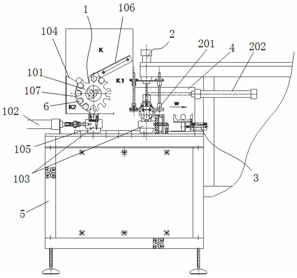
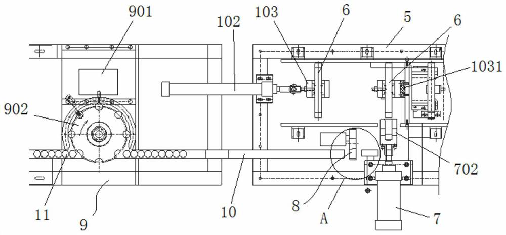
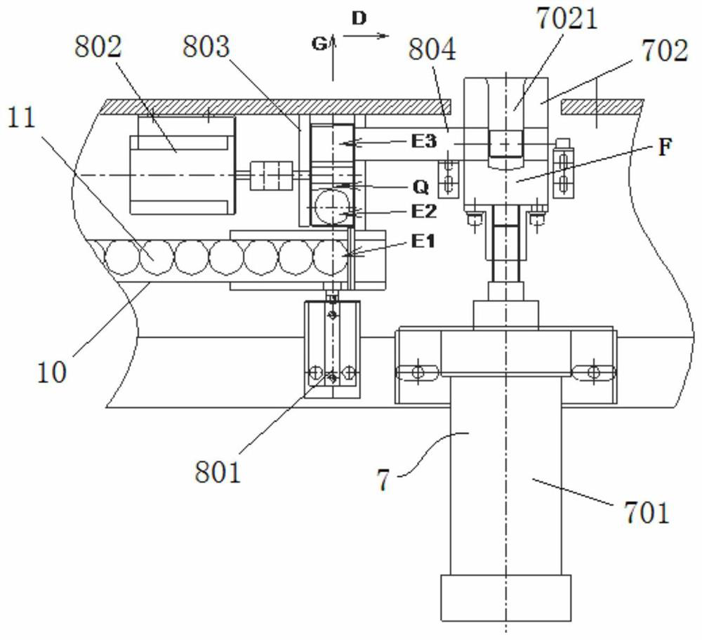
[0033] Such as Figure 1~6 As shown, the present invention includes a melt tube input mechanism 1, an end cap reversal input mechanism 8, a cap pressing mechanism 7, a feeding mechanism 2 and a transition mechanism 3. The melt pipe input mechanism 1, an end cap reversal input mechanism 8, a pressure cap The mechanism 7, the unloading mechanism 2 and the transition mechanism 3 are all installed on a frame 5, wherein the melt tube 6 is fed into the capping station on the frame 5 through the melt tube input mechanism 1, and the end cap flip input mechanism 8 An end cap transmission channel 10 is connected to the automatic gluing mechanism 9 in the previous process, and the end cap 11 that completes the gluing operation through the automatic gluing mechanism 9 has an opening facing upward along the end cap transmission channel 10 Move to the end cap reversing input mechanism 8 in ...


PUM


Abstract

The invention relates to the technical field of fuse production, in particular to an automatic cap pressing mechanism of a fuse. The mechanism comprises a fusion tube input mechanism, an end cap overturning input mechanism, a cap pressing mechanism, a discharging mechanism and a transition mechanism. The fusion tube input mechanism comprises an input gear disc and an input cylinder; a to-be-pressed fusion tube is fed into the cap pressing station through the fusion tube input mechanism; the end cap overturning input mechanism comprises an end cap pushing-in air cylinder, an end cap overturningmotor, an overturning base and an end cap roller path; the end cap is pushed into the overturning notch of the overturning base through the end cap pushing-in cylinder; the overturning base is drivenby the end cap overturning motor to overturn, after overturning, an inclined face Q in the overturning notch is connected with the input end of the end cap roller path, the cap pressing mechanism isprovided with a cap pressing base, when the cap pressing base retreats, the notch in the cap pressing base is connected with the output end of the end cap roller path, and the fusion tube completing cap pressing is conveyed into the transition mechanism through the discharging mechanism. The mechanism can be matched with automatic gluing equipment to achieve automatic cap pressing operation, and the purpose of full-automatic production of fuses is achieved.

Description

Technical field [0001] The invention relates to the field of fuse production, in particular to a fuse automatic cap pressing mechanism. Background technique [0002] The fuse includes a fuse core, a fuse tube and an end cap, wherein the fuse core is placed in the fuse tube, and the end of the fuse tube is press-fitted with the end cap to achieve sealing. At present, the fuse assembly process is basically manual work. Although the technical index can basically meet the standard during the inspection, there are many shortcomings: [0003] 1. Relying on manual assembly production, the production efficiency is relatively low; [0004] 2. The product quality and appearance after assembly are not uniform enough, and the pass rate is relatively low; [0005] 3. The manual pressure cap is unevenly applied, resulting in a relatively high damage rate; [0006] 4. In order to ensure the end caps are firmly fixed, it is necessary to apply glue inside the end caps, but the manual glue application ...

Claims


Application Information

Patent Timeline
Patent Type & Authority Applications(China)
IPC IPC(8): H01H69/02
CPCH01H69/02
Inventor 李涛昌陆振东刘红于波张桂俊赫鑫兰姚昀辰
Owner 大连北方真空开关有限公司
Why Eureka
Eureka Blog
Learn More