Metal shell button type lithium ion battery

A technology of lithium-ion batteries and metal shells, which is applied in the direction of batteries, cylindrical shell batteries/batteries, secondary batteries, etc., can solve the problem that the good sealing of the inner shell and the outer shell cannot be fully guaranteed, and the battery product cannot make full use of the diameter direction space, battery products can not make full use of the axial space and other issues, to achieve the effect of simple structure, improved energy density, and good sealing

Pending Publication Date: 2020-09-18
CHONGQING VDL ELECTRONICS
View PDF0 Cites 6 Cited by
  • Summary
  • Abstract
  • Description
  • Claims
  • Application Information

AI Technical Summary

Problems solved by technology

[0002] At present, when most battery manufacturers make thin metal shell lithium secondary batteries, the outer shell of the battery cell adopts a circular metal shell, and its structure is divided into three layers: an inner shell, an outer shell, and a sealing ring. Therefore, in the prior art Lithium-ion batteries occupy a lot of space in the radial direction, resulting in that the battery product cannot make full use of the space in the radial direction, so there is a technical problem of low energy density of the battery. The seal between the inner shell and the outer shell adopts an R angle Sealing technology, which relies on compressed plastic sealing rings to achieve sealing
However, the existing technical means are not very accurate in measuring the R angle, so the good sealing between the inner shell and the outer shell cannot be fully guaranteed, and there are technical problems of low product reliability and low pass rate
In addition, the inner shell and the outer shell of the steel shell are used as the positive and negative electrodes respectively, and the battery product is prone to short circuit problems.
[0003] In order to improve the above technical problems, a new structure has also been developed in recent years, that is, a similar structure to the current power aluminum case battery is adopted, such as figure 1 Shown is a battery product in the prior art, which uses a single-layer metal casing 83 as the negative electrode, and an aluminum cap 81 of another polarity is arranged on one side of the metal casing 83, and the insulation treatment method between the metal casing 83 and the aluminum cap 81 is as follows: The riveted structure, the biggest shortcoming of the riveted structure is that there are five layers of structure on the axial side of the battery core: aluminum cap 81, first insulating layer 82, metal shell 83, second insulating layer 84 and rivets 85, the five layers The structure occupies too much space, usually more than 1mm, so the battery product cannot make full use of the axial space, and there is a technical problem of low energy density of the battery

Method used


Image

  • Metal shell button type lithium ion battery
  • Metal shell button type lithium ion battery
  • Metal shell button type lithium ion battery

Examples


Embodiment 1

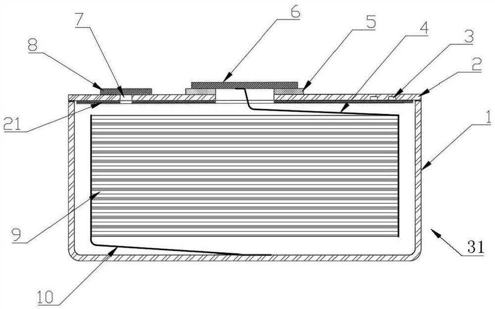
[0025] The invention provides a metal shell button lithium ion battery, such as figure 2 Shown is a schematic cross-sectional view of the battery, which includes a metal case 31, a battery cell 9 installed inside the metal case 31, a terminal 6 installed outside the metal case 31, and a terminal 6 installed between the metal case 31 and the terminal. The insulator 5 between the 6 and the metal shell 31 and the terminal 6 are insulated and sealed respectively, and the electric core 9 is provided with at least one first pole ear that is electrically connected to the metal shell 31 and has positive or negative polarity 10. The electric core 9 is also provided with at least one second tab 4 electrically connected to the terminal 6 and having negative or positive polarity, and the polarity of the metal shell 31 is opposite to that of the terminal 6, The metal shell 31 and the terminal 6 are hermetically connected to the insulator 5 by heat sealing or adhesive respectively, wherein...

Embodiment 2

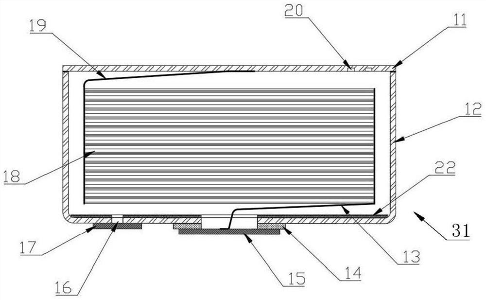
[0034] The present invention provides another metal shell button lithium ion battery, which includes a metal shell 31, such as image 3 Shown is a schematic cross-sectional view of the battery, the cell 18 installed inside the metal case 31, the terminal 15 installed outside the metal case 31, installed between the metal case 31 and the terminal 15 and respectively connected to the metal case 31. The shell 31 and the terminal 15 are insulated and sealed insulators 14. The electric core 18 is provided with at least one first tab 19 electrically connected to the metal shell 31 and having positive or negative polarity. The electric core 18 There is also provided at least one second tab 13 electrically connected to the terminal 15 and having negative or positive polarity. The polarity of the metal shell 31 is opposite to that of the terminal 15. The metal shell 31 and the The terminals 15 are hermetically connected to the insulator 14 by heat sealing or adhesive respectively, wher...


PUM


Abstract

The invention relates to the field of lithium batteries, and discloses a metal shell button type lithium ion battery. The battery comprises a metal shell, a battery cell which is arranged in the metalshell, a terminal arranged on the outer side of the metal shell, and an insulating part arranged between the metal shell and the terminal and is insulated and sealed with the metal shell and the terminal respectively; at least one first tab which is electrically connected with the metal shell and has positive polarity or negative polarity is arranged on the battery cell; the battery cell is alsoprovided with at least one second tab which is electrically connected with the terminal and has negative polarity or positive polarity; the metal shell and the terminal are connected with the insulating part in a heat sealing or bonding manner; the metal shell serves as one pole, and the terminal serves as the other pole; the occupied space of the battery structure is small in the axial directionand the radial direction of the battery cell, the energy density of the battery is improved, and the lithium ion battery has the advantages of being simple in structure, high in sealing reliability and high in energy density and meets the efficient production requirement.

Description

technical field [0001] The invention relates to the field of lithium batteries, in particular to a metal shell button lithium ion battery. Background technique [0002] At present, when most battery manufacturers make thin metal shell lithium secondary batteries, the outer shell of the battery cell adopts a circular metal shell, and its structure is divided into three layers: an inner shell, an outer shell, and a sealing ring. Therefore, in the prior art Lithium-ion batteries occupy a lot of space in the radial direction, resulting in that the battery product cannot make full use of the space in the radial direction, so there is a technical problem of low energy density of the battery. The seal between the inner shell and the outer shell adopts an R angle Sealing technology, which relies on compressed plastic sealing rings to achieve sealing. However, the existing technical means are not very accurate in measuring the R angle, so the good sealing between the inner shell and...

Claims


Application Information

Patent Timeline
Patent Type & Authority Applications(China)
IPC IPC(8): H01M2/02H01M2/06H01M2/08H01M2/30H01M2/34H01M10/0525H01M10/058
CPCH01M10/0525H01M10/058Y02E60/10H01M10/0427H01M50/193H01M50/55H01M50/188H01M50/636H01M50/30Y02P70/50H01M50/56H01M50/564H01M50/197H01M50/119H01M50/164H01M50/109H01M50/153H01M50/578H01M50/3425H01M50/609H01M2200/20H01M50/531H01M50/116H01M50/543H01M50/183
Inventor 邓亚西
Owner CHONGQING VDL ELECTRONICS
Why Eureka
Try Eureka