

Method for mutually connecting circuit boards
A technology of interconnection and circuit board, which is applied in the direction of circuit, electrical component assembly printed circuit, printed circuit, etc., and can solve the problem of increasing production steps
- Summary
- Abstract
- Description
- Claims
- Application Information
AI Technical Summary
Problems solved by technology
Method used
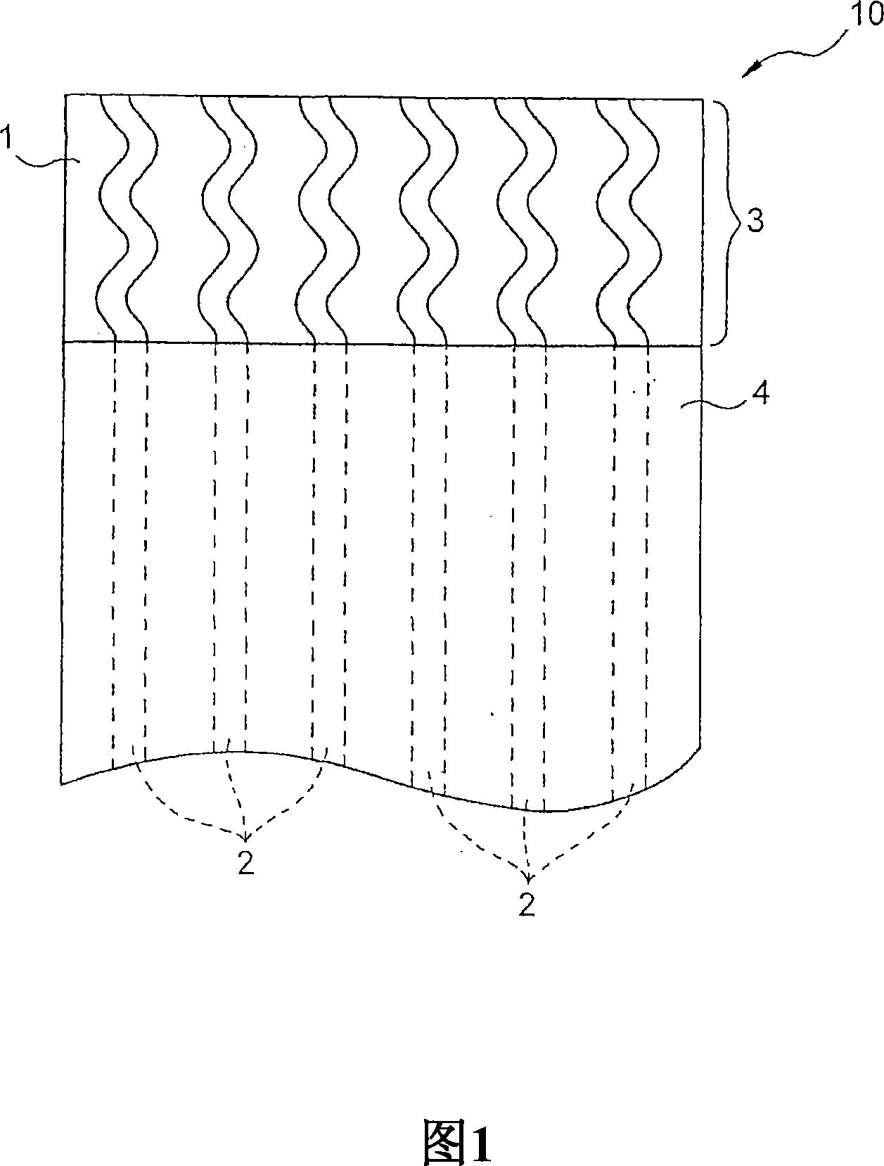
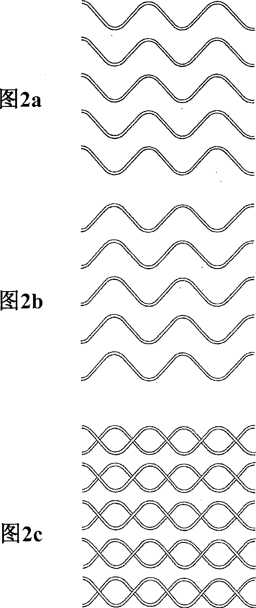
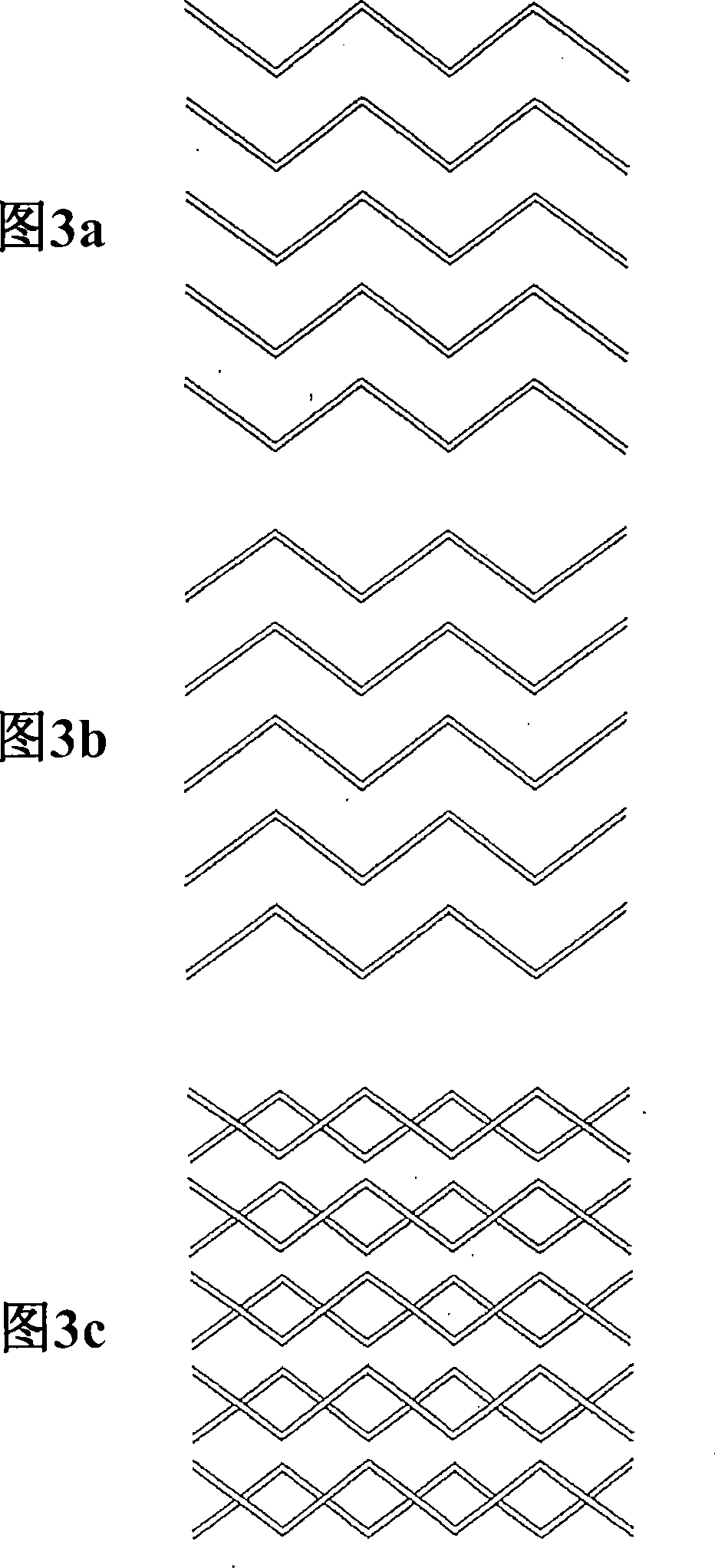
Image

Examples
example
[0042] The compositions shown in Table 1 below were coated on a polyester film treated with silicone resin, and dried to form a film having a thickness of 30 μm.
[0043] Table 1
[0044] Table 1: Resin Composition
[0045] Element
parts by weight
YP50S
30
DER332
34
G402
30
BAFL
16.4
MC600
20
EXL2314
80
THF
600
[0046] Phenoxy resin:
[0047] YP50S, manufactured by Tohto Kasei Co., Ltd., average molecular weight: 11,800
[0048] Epoxy resin:
[0049] DER332, manufactured by Japan Dow Chemical Co., Ltd., amount of epoxy: 174
[0050] Polycaprolactone modified epoxy resin:
[0051] G402, manufactured by Daicel Chemical Industry Co., Ltd., amount of epoxy: 1,350
[0052] Diphenylamine fluorene:
[0053] BAFL, Nippon Steel Chemical Co., Ltd.
[0054] Melamine isocyanurate complex:
[0055] MC-600, manufactured by Nissan Chemical Industry Co., Ltd.
[0056] Ac...
PUM
| Property | Measurement | Unit |
|---|---|---|
| Viscosity | aaaaa | aaaaa |
Abstract
Description
Claims
Application Information