

Punching device for chain pin
A punching device and pin shaft technology, which is applied in the direction of boring/drilling, drilling/drilling equipment, large fixed members, etc., can solve manual problems, avoid displacement deviation, save costs, and avoid punching positions wrong effect
- Summary
- Abstract
- Description
- Claims
- Application Information
AI Technical Summary
Problems solved by technology
Method used
Image

Examples
Embodiment
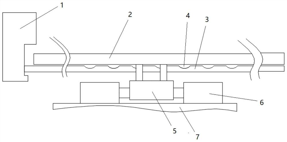
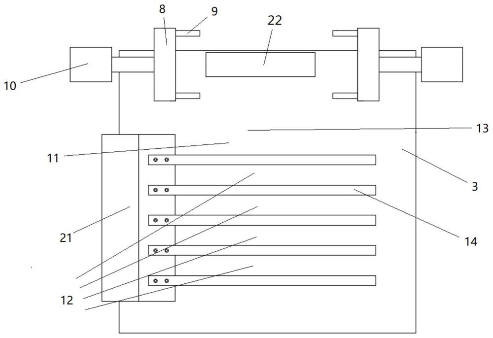
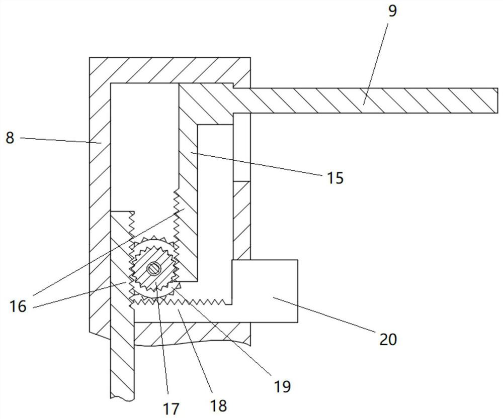
[0019] like figure 1 , figure 2 , image 3 In the shown embodiment, a chain pin punching device includes a punching assembly 1 and a transmission assembly. The transmission assembly includes a base plate 3, a push plate 2 for pushing the pin shaft 22, a power assembly, and a power assembly for supporting the power assembly. The frame body 7, the base plate 3 is provided with a groove structure 4 for accommodating the pin shaft 22, the power assembly includes a horizontal power device 6 and a longitudinal power device 5, the horizontal power device 6 and the longitudinal power device 5 are cylinder devices respectively, and the horizontal power device The fixed end of the device 6—the cylinder barrel of the cylinder and the frame body 7 are fixedly connected by bolts, the power output end of the transverse power device 6—the piston rod of the cylinder is fixedly connected with the fixed end of the longitudinal power device 5, and the longitudinal power device The power outpu...
PUM
 Abstract
Description
Claims
Application Information