Energy accumulator vertically-arranged balance hydro-pneumatic suspension

A technology of oil and gas suspension and accumulator, applied in the field of hydraulic machinery, can solve the problems of heavy body structure, complex mechanical balance suspension structure, increased maintenance cost, etc., so as to improve reliability, optimize pipeline layout, and restrain along the path. The effect of drag loss

Pending Publication Date: 2020-09-22
CHINA NORTH VEHICLE RES INST
View PDF0 Cites 1 Cited by
  • Summary
  • Abstract
  • Description
  • Claims
  • Application Information

AI Technical Summary

Problems solved by technology

[0003] At present, most mining vehicles in China use the 6X4 drive mode. The two rear axles are relatively close to each other and are mainly used to carry the weight of the cargo. Most of the existing technologies use the structure of leaf springs to achieve balanced suspension through structural parts. Function, that is, the bearing capacity of the two axles compensates each other, effectively suppresses the ultimate impact load of a single axle, and avoids the phenomenon of axle damage, but the structure of the mechanical balance suspension is complicated, and the body structure is very heavy. When subjected to heavy loads, the average service life is only 3 months, which greatly increases the maintenance cost and becomes the main problem and technical shortcoming of mining vehicles

Method used


Image

  • Energy accumulator vertically-arranged balance hydro-pneumatic suspension
  • Energy accumulator vertically-arranged balance hydro-pneumatic suspension
  • Energy accumulator vertically-arranged balance hydro-pneumatic suspension

Examples


Embodiment Construction

[0029] The present invention will be described in detail below with reference to the accompanying drawings and examples.

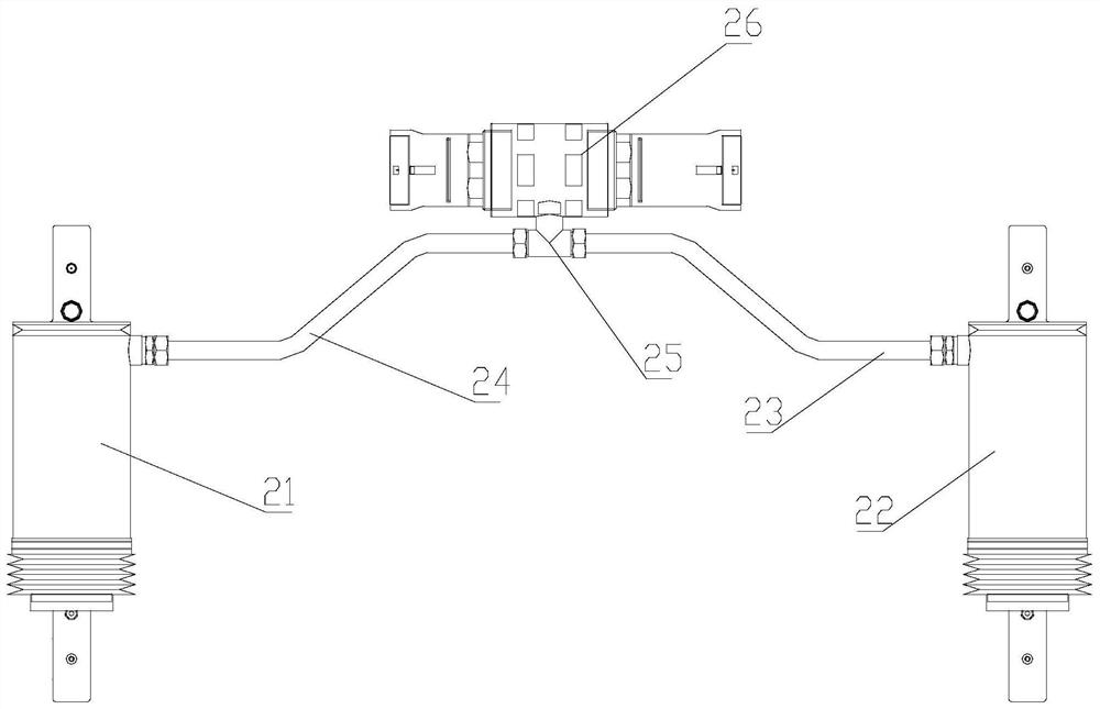
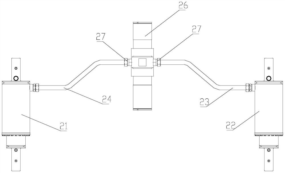
[0030] The invention designs a balanced oil-gas suspension structure, which has wide application prospects in the fields of mining machinery and multi-axle heavy-duty vehicles. Such as figure 1 with 5 As shown, it is a schematic diagram of the horizontal balance oil-air suspension structure of the accumulator. The communication port 18 of the main oil chamber of the front oil-gas spring 21 is connected to one end of the front balance pipeline 24, and the communication port 18 of the main oil chamber of the rear oil-gas spring 22 is connected to the One end of the rear balance pipeline 23 is connected, and further, the other end of the front balance pipeline 24 and the other end of the rear balance pipeline 23 are connected with the oil inlet of the accumulator 26 through the three-way joint 25, thereby forming a balance suspension. The internal high-pres...


PUM


Abstract

The invention discloses an energy accumulator vertically-arranged balance hydro-pneumatic suspension, and belongs to the technical field of hydraulic machinery. The suspension comprises a front hydro-pneumatic spring, a front balance pipeline, a rear hydro-pneumatic spring, a rear balance pipeline, an energy accumulator and pipeline joints. A main oil cavity oil port of the front hydro-pneumatic spring is connected to one end of a front balance pipeline, and the other end of the front balance pipeline is connected to a first oil inlet of the energy accumulator through the pipeline joint. A main oil cavity oil port of the rear hydro-pneumatic spring is connected to one end of the rear balance pipeline, and the other end of the rear balance pipeline is connected to a second oil inlet of theenergy accumulator through the pipeline joint to form balance suspension. A front wheel hydro-pneumatic spring oil chamber is communicated with a rear wheel hydro-pneumatic spring oil chamber, the energy accumulator is arranged outside, the single-wheel impact load is greatly reduced, the tire grounding capacity is remarkably improved, and wide application prospects are achieved in the fields of mining machineries and the like.

Description

technical field [0001] The invention relates to a vertically balanced oil-air suspension of an energy accumulator, which belongs to the technical field of hydraulic machinery. Background technique [0002] The oil-air suspension is mainly composed of oil-air springs, which integrate elasticity and damping elements. At the same time, the cylinder has a certain guiding effect, and the space required for the car body layout is small. With its superior nonlinear elastic characteristics and good vibration damping performance, it can To meet the ride comfort requirements of engineering vehicles to the greatest extent. From the point of view of its overall structure, the oil-air suspension systems currently used on engineering vehicles mainly include two types: independent and interconnected; from the form of oil-air springs, they are divided into single-chamber oil-gas separation type and double-air chamber oil-gas separation type. , multi-stage pressure type and oil-gas mixed ty...

Claims


Application Information

Patent Timeline
Patent Type & Authority Applications(China)
IPC IPC(8): B60G11/26B60G11/30
CPCB60G11/265B60G11/30B60G2202/154
Inventor 陈轶杰韩小玲郑冠慧张亚峰张旭赵宁徐梦岩万义强
Owner CHINA NORTH VEHICLE RES INST
Why Eureka
Try Eureka