
Assembly type steel structure weld joint detection device

A weld detection and steel structure technology, applied in the field of assembled steel structure weld detection devices, can solve the problems of manual hand-held detection, inconvenient operation, time-consuming and laborious, etc., and achieve the effect of efficient weld detection and defect location positioning

Inactive Publication Date: 2020-09-22
安徽匠桥财务咨询服务有限公司
View PDF0 Cites 2 Cited by
  • Summary
  • Abstract
  • Description
  • Claims
  • Application Information

AI Technical Summary

Problems solved by technology

[0002] The prefabricated building refers to the transfer of a large number of on-site operations in the traditional construction method to the factory, where the building components and accessories are processed and manufactured, transported to the construction site, and assembled and installed on site through reliable connection methods. , among them, the prefabricated steel structure is widely used in various buildings because of its unique performance. The construction steel structure usually needs to be welded when it is used, and the welds and cracks that may be caused by welding are obviously harmful to the use of steel structures. The safety performance is very important, so it is necessary to detect the weld seam, and the traditional weld seam inspection device often needs to be manually hand-held to complete the inspection, which is time-consuming and laborious, and the detection efficiency is low. The detection efficiency and labor intensity cannot meet the needs of mass welding. Due to the various styles of welds in steel structures, the traditional weld detection device needs to reach and align with the welding position and observe the data in real time, resulting in inconvenient operation and poor practicability

Method used


Image

  • Assembly type steel structure weld joint detection device
  • Assembly type steel structure weld joint detection device

Examples


Embodiment Construction

[0025] In order to make the purpose, technical solutions and advantages of the present disclosure clearer, the present disclosure will be further described in detail below in conjunction with specific embodiments.

[0026] It should be noted that, unless otherwise defined, the technical terms or scientific terms used in one or more embodiments of the present specification shall have ordinary meanings understood by those skilled in the art to which the present disclosure belongs. "First", "second" and similar words used in one or more embodiments of the present specification do not indicate any order, quantity or importance, but are only used to distinguish different components. "Comprising" or "comprising" and similar words mean that the elements or items appearing before the word include the elements or items listed after the word and their equivalents, without excluding other elements or items. Words such as "connected" or "connected" are not limited to physical or mechanica...


PUM


Abstract

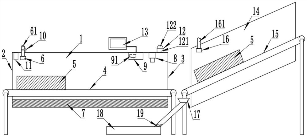
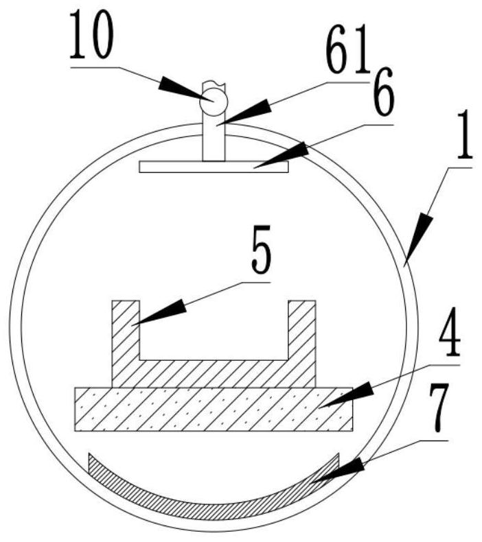
One or more embodiments of the invention provide an assembly type steel structure weld joint detection device. The device comprises a detection chamber. A conveying belt penetrates through the hollowinterior of the detection cavity. Through the conveyor belt, the steel structure can be conveyed through the hollow interior of the detection cavity. Through the magnetic powder spray head close to the feeding hole, magnetic powder can be uniformly sprayed on the steel structure. A magnetic field is generated through an electromagnetic device at the bottom end in the detection cavity, and the steel structure in the detection cavity can be magnetized. A leakage magnetic field is generated at a weld joint or a crack defect on the surface of the steel structure, to absorb and collect magnetic powders. The image information of the steel structure can be shot through the image shooting device close to the discharging opening, the image information is transmitted to the image processor, the grayvariance of the image information is processed and analyzed through the image processor so that the gathered magnetic powder can be detected, automatic batch detection can be achieved, detection is visual and convenient, and the detection efficiency is high.

Description

technical field [0001] One or more embodiments of this specification relate to the technical field of fabricated steel structure detection, and in particular to a weld seam detection device of fabricated steel structure. Background technique [0002] The prefabricated building refers to the transfer of a large number of on-site operations in the traditional construction method to the factory, where the building components and accessories are processed and manufactured, transported to the construction site, and assembled and installed on site through reliable connection methods. , among them, the prefabricated steel structure is widely used in various buildings because of its unique performance. The construction steel structure usually needs to be welded when it is used, and the welds and cracks that may be caused by welding are obviously harmful to the use of steel structures. The safety performance is very important, so it is necessary to detect the weld seam, and the tradi...

Claims


Application Information

Patent Timeline
Patent Type & Authority Applications(China)
IPC IPC(8): G01N27/84B05B13/04B05B12/32
CPCB05B13/04B05B12/32G01N27/84
Inventor 吴浩凤志民
Owner 安徽匠桥财务咨询服务有限公司
Learn More