
Satellite navigation signal design method based on pseudo-random Chirp

A satellite navigation signal and design method technology, applied in satellite radio beacon positioning systems, instruments, measuring devices, etc., can solve the problems of inaccurate carrier phase and long capture time of navigation signals, etc., to reduce multiple access interference, Shorter capture time and effects of Doppler tolerance

Active Publication Date: 2020-09-22
BEIJING AUTOMATION CONTROL EQUIP INST
View PDF6 Cites 3 Cited by
  • Summary
  • Abstract
  • Description
  • Claims
  • Application Information

AI Technical Summary

Problems solved by technology

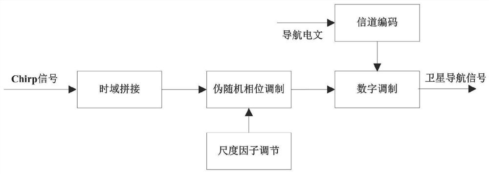
[0005] Aiming at the technical problems existing in the prior art, such as long navigation signal capture time and inaccurate download wave phase under high dynamic conditions, the present invention proposes a pseudo-random Chirp-based satellite navigation signal design method, through pseudo-random phase modulation, reverse modulation The time-domain splicing of frequency Chirp signals and the physical layer security coding of navigation messages make the designed satellite navigation signals have both Doppler tolerance, multiple access characteristics and physical layer security, and fundamentally combine navigation signals The acquisition process is reduced to a one-dimensional search in the time domain, which reduces the acquisition time, improves the dynamic stress of the navigation signal, and meets the carrier phase estimation requirements under high dynamic conditions.

Method used


Image

  • Satellite navigation signal design method based on pseudo-random Chirp
  • Satellite navigation signal design method based on pseudo-random Chirp
  • Satellite navigation signal design method based on pseudo-random Chirp

Examples


Embodiment Construction

[0031] The present invention will be described in detail below in conjunction with the accompanying drawings and embodiments.

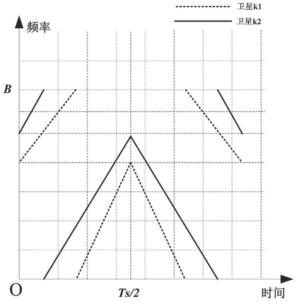
[0032] In order to meet the multiple access performance of satellite navigation signals in the present invention, the navigation signal reference signal of each satellite is spliced ​​by two sections of Chirp signals with the same symbol duration and the same spectrum width but completely opposite modulation frequencies, wherein each section of the Chirp signal It is also spliced ​​by two Chirp signals with the same modulation frequency but different starting frequencies. The spliced ​​reference signals of different satellites all have the same symbol duration and symbol bandwidth, but have different starting frequencies or modulation frequencies. figure 2 A schematic diagram of the time-frequency characteristics of two satellite reference signals is given.

[0033] Secondly, in order to improve the security of the navigation signal and further redu...


PUM


Abstract

The invention provides a satellite navigation signal design method based on pseudo-random Chirp. A navigation signal reference signal of each satellite is formed by splicing two sections of Chirp signals with the same symbol duration, the same frequency spectrum width and completely opposite modulation frequencies, and each section of Chirp signal is formed by splicing two sections of Chirp signals with the same modulation frequency and different initial frequencies; pseudo-random phase modulation of the reference signal of each satellite is carried out; the coded navigation message is modulated to the designed pseudo-random Chirp signal to obtain a satellite navigation signal. The method has the characteristics of large Doppler tolerance, multiple access and physical layer security. The method can fundamentally reduce the dimension of the receiver capture process into time domain one-dimensional search, shortens the capture time, improves the dynamic stress of a receiver, meets the carrier phase estimation requirements under high dynamic conditions, and is suitable for the fields of satellite navigation systems, pseudo-satellite positioning auxiliary systems, indoor positioning systems and the like.

Description

technical field [0001] The invention belongs to the field of navigation signal design, and relates to a method for designing satellite navigation signals by utilizing Chirp signals. Background technique [0002] The satellite navigation receiver of the traditional direct sequence spread spectrum system needs to go through a long time of pseudo-code-frequency offset two-dimensional search to capture the navigation signal in a highly dynamic environment. Even if the mainstream partial matched filtering and frequency-domain FFT technology is used to realize the parallel search of code phase and partial frequency units, the acquisition time of a single satellite is still much longer than its time-domain search length, and the receiver's first positioning time even reaches Minutes. In addition, in order to obtain centimeter and decimeter-level positioning information, the satellite receiver needs to measure the accurate carrier phase of the navigation signal. However, the pseud...

Claims


Application Information

Patent Timeline
IPC IPC(8): G01S19/24G01S19/29G01S19/37
CPCG01S19/24G01S19/29G01S19/37
Inventor 王腾李峰
Owner BEIJING AUTOMATION CONTROL EQUIP INST
Learn More