
Composite brightness enhancement film back coating surface structure and manufacturing method

A technology of surface structure and enhancement film, which is applied in optics, optical components, nonlinear optics, etc., can solve problems such as structural pits on the back coating surface, and achieve the effect of improving shielding, increasing the value of enhancement gain, and scientific and reasonable design

Inactive Publication Date: 2020-09-22
CCS (SHANGHAI) FUNCTIONAL FILMS IND CO LTD
View PDF7 Cites 1 Cited by
  • Summary
  • Abstract
  • Description
  • Claims
  • Application Information

AI Technical Summary

Problems solved by technology

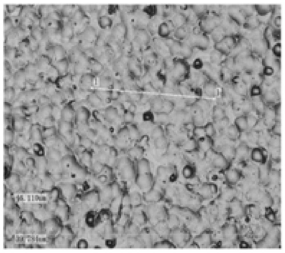
However, this kind of back-coated surface structure is an ordinary sandblasting structure made by ordinary sandblasting equipment, and the formed back-coated surface structure has pits

Method used


Image

  • Composite brightness enhancement film back coating surface structure and manufacturing method
  • Composite brightness enhancement film back coating surface structure and manufacturing method
  • Composite brightness enhancement film back coating surface structure and manufacturing method

Examples


Embodiment 1

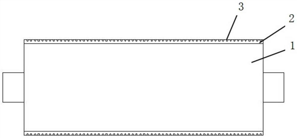
[0033] This embodiment is a back-coating surface structure of a composite light-enhancing film, including a base material, and the base material has a pair of opposite surfaces, which are respectively a light-incoming surface and a back-coating surface. The back coating surface is a rough prism surface, which is processed by an improved forming roller. The rough prism surface has multiple convex points, and the surface of the convex points is reflective. The improved forming roll includes a base roll 1 and a nickel-phosphorus layer 2 electroplated on its outside. The surface of the base roll 1 is flattened before electroplating, and thread cutting and engraving is performed on the nickel-phosphorus layer 2 with a diamond tool after electroplating. , the cutting depth of the diamond tool is 2-5um, the cutting frequency is 15000-20000HZ, the cutting depth and the cutting frequency are both random; the surface of the nickel phosphorus layer 2 has a micro concave structure 3 after ...

Embodiment 2

[0046] This embodiment is basically the same as Embodiment 1, except that the nickel-phosphorus layer has a thickness of 230mm and a hardness of 572HB.

[0047] The lightening gains of this embodiment and the common sandblasting structure under different hazes are shown in the following table:

[0048] Grace gain Haze 10% Haze 15% Haze 20% Haze 30% Ordinary sandblasting structure 100% 100% 100% 100% The structure of this embodiment 102.4% 102.3% 103% 102.2%

[0049] On the premise of the same shielding performance, the structural design of this embodiment can increase the brightness enhancement gain value of the brightness enhancement film by 2-3%.

Embodiment 3

[0051] This embodiment is basically the same as Embodiment 1, except that the thickness of the nickel-phosphorus layer is 250mm, and the hardness is 574HB.

[0052] The lightening gains of this embodiment and the common sandblasting structure under different hazes are shown in the following table:

[0053] Grace gain Haze 10% Haze 15% Haze 20% Haze 30% Ordinary sandblasting structure 100% 100% 100% 100% The structure of this embodiment 102.3% 103% 102.5% 102.1%

[0054] On the premise of the same shielding performance, the structural design of this embodiment can increase the brightness enhancement gain value of the brightness enhancement film by 2-3%.


PUM

PropertyMeasurementUnit
Thicknessaaaaaaaaaa
Thicknessaaaaaaaaaa
Thicknessaaaaaaaaaa

Abstract

The invention discloses a composite brightness enhancement film back coating surface structure and a manufacturing method. The composite brightness enhancement film back coating surface structure comprises a base material, wherein the base material is provided with a pair of opposite surfaces which are respectively a light incoming surface and a back coating surface, the back coating surface is arough prism surface, and the rough prism surface is processed by an improved forming roller; the improved forming roller comprises a base roller and a nickel-phosphorus layer electroplated on the outer side of the base roller, the surface of the base roller is flattened before electroplating, the nickel-phosphorus layer is subjected to thread cutting and carving treatment through a diamond cutterafter electroplating, the cutting depth of the diamond cutter is 2-5 micrometers, the cutting frequency of the diamond cutter is 15000-20000HZ, and a micro-concave structure is formed on the surface of the nickel-phosphorus layer after thread cutting and carving treatment. The structure design is scientific and reasonable, the rough prism surface is obtained through processing improvement of the forming roller, diffuse reflection propagation of light can be reduced while the shielding performance is improved, the brightness enhancement effect is further guaranteed, and the brightness enhancement gain value can be increased by 2-3%.

Description

technical field [0001] The invention relates to the technical field of liquid crystal display, in particular to a back coating surface structure and a manufacturing method of a composite brightness enhancement film. Background technique [0002] With the popularization of TFT-LCD liquid crystal display technology, the demand for its backlight module and its related optical film is also increasing. With the impact of OLED new technology, the industry has lowered the price of LCD liquid crystal displays, corresponding raw materials also need lower prices, and need to reduce costs. The brightness enhancement film used in the backlight module of the LCD liquid crystal display is also bound to reduce the cost. The brightness enhancement film mainly plays the role of brightness enhancement and shielding in the backlight module. The structure of the back-coated surface has an atomization effect, and there is a certain amount of fog, which is mainly to improve the shielding propert...

Claims


Application Information

Patent Timeline
IPC IPC(8): G02B5/04G02F1/13357
CPCG02B5/045G02F1/1336
Inventor 周鹏沈渊刁全利王磊孙亮
Owner CCS (SHANGHAI) FUNCTIONAL FILMS IND CO LTD
Learn More