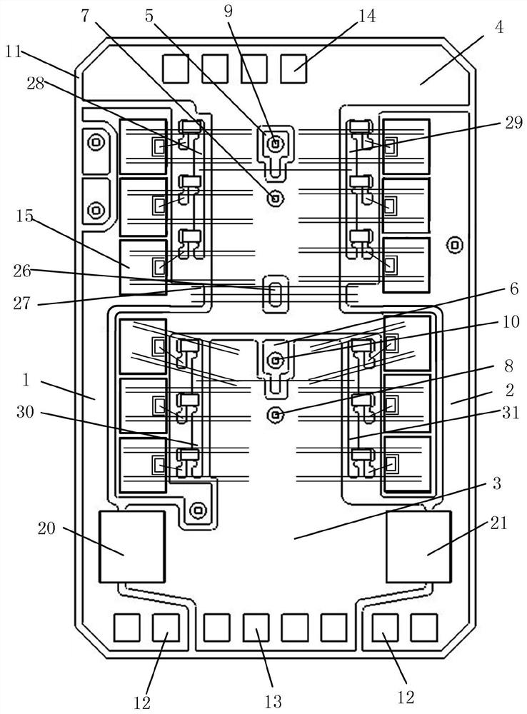
Power semiconductor module substrate and its applied electric locomotive

A power semiconductor and power technology, applied in the direction of semiconductor devices, semiconductor/solid-state device components, circuits, etc., can solve the problems of voltage oscillation, power device turn-off voltage oscillation, device damage, etc., to extend service life, ensure safety, The effect of suppressing voltage spikes and oscillations

Active Publication Date: 2022-07-01
LEADRIVE TECH (SHANGHAI) CO LTD
View PDF0 Cites 0 Cited by
  • Summary
  • Abstract
  • Description
  • Claims
  • Application Information

AI Technical Summary

Problems solved by technology

During the commutation process, due to the current change rate di / dt, an induced voltage will be generated on the stray inductance. The induced voltage is ΔV=(Lc1+Lc2+Lc3) di / dt, and the voltage on the stray inductance is superimposed on the upper tube S1, resulting in a voltage peak Vpeak =Vdc+(Lc1+Lc2+Lc3) di / dt, the voltage exceeding the breakdown voltage Vces of the power device will cause the device to be damaged
At the same time, the stray inductance and the junction capacitance of the power device form an LC oscillation circuit, which causes the technical problem of the shutdown voltage oscillation of the power device
[0003] It can be seen that the existing power semiconductor substrate scheme has the technical problem that the power semiconductor device is subjected to excessive voltage or voltage oscillation during the commutation process

Method used


Image

  • Power semiconductor module substrate and its applied electric locomotive
  • Power semiconductor module substrate and its applied electric locomotive

Examples


Embodiment Construction

[0037] The embodiments of the present disclosure will be described in detail below with reference to the accompanying drawings.

[0038] The embodiments of the present disclosure are described below through specific specific examples, and those skilled in the art can easily understand other advantages and effects of the present disclosure from the content disclosed in this specification. Obviously, the described embodiments are only some, but not all, embodiments of the present disclosure. The present disclosure can also be implemented or applied through other different specific embodiments, and various details in this specification can also be modified or changed based on different viewpoints and applications without departing from the spirit of the present disclosure. It should be noted that the following embodiments and features in the embodiments may be combined with each other under the condition of no conflict. Based on the embodiments in the present disclosure, all oth...


PUM


Abstract

Embodiments of the present disclosure provide a power semiconductor module substrate and an electric locomotive to which it is applied, belonging to the technical field of semiconductors. It includes: a substrate main body, including a rectangular substrate and a power metal coating, a first welding area is provided on the first power metal coating, a second welding area is provided on the second power metal coating, and a third power metal coating is provided A third welding area and a fourth welding area are arranged on the layer; the absorption capacitor group, the first absorption capacitor includes a first conductive pin and a second conductive pin, and the second absorption capacitor includes a third conductive pin and a fourth conductive lead feet, the first conductive pin is electrically connected to the first bonding area, the second conductive pin is electrically connected to the third bonding area, the third conductive pin is electrically connected to the fourth bonding area, and the fourth conductive pin is electrically connected to the The second welding area is electrically connected. In this way, the added absorption capacitor effectively suppresses the voltage peak and oscillation during the switching process of the power device by absorbing the large voltage of the peak, thereby ensuring the safety of the power device.

Description

technical field [0001] The present disclosure relates to the field of semiconductor technology, and in particular, to a power semiconductor module substrate and an electric locomotive to which it is applied. Background technique [0002] At present, in the application of DC to AC, the DC power supply is connected to the power module through the positive and negative busbars, and the busbar stray inductance is directly related to the voltage peak value that the power device withstands when it is turned off. In the half-bridge power module, S1 and S2 are switching devices connected in series in the power module, Lc1 is the stray inductance between the positive busbar and the power module terminals, Lc2 is the stray inductance between the negative busbar and the power module terminals, and Lc3 is the inside of the power module of confusion. At the moment when S1 is turned off, the current of S1 is commutated to the freewheeling diode of the lower tube S2. Due to the clamping a...

Claims


Application Information

Patent Timeline
Patent Type & Authority Patents(China)
IPC IPC(8): H01L25/16H01L23/498
CPCH01L25/16H01L23/49838H01L2224/49111H01L2224/49175
Inventor 李武华周宇罗皓泽高洪艺夏雨昕沈捷
Owner LEADRIVE TECH (SHANGHAI) CO LTD
Why Eureka
Try Eureka