
Split conductor subspan oscillation suppression device

A technology of split wires and suppression devices, which is applied in the direction of mechanical vibration attenuation devices, mechanical equipment, fluid flow, etc., can solve the problems of affecting normal and safe power supply, high economic cost, and heavy workload, and achieves the suppression of sub-gap oscillation of split wires , reduce wear and tear, and facilitate installation

Pending Publication Date: 2020-09-22
CHINA ELECTRIC POWER RES INST +1
View PDF0 Cites 0 Cited by
  • Summary
  • Abstract
  • Description
  • Claims
  • Application Information

AI Technical Summary

Problems solved by technology

Practice has shown that the sub-gap oscillation phenomenon of transmission lines in windy areas is still serious, and the adjustment of the distance between the spacers for the entire transmission line that has been built will not only affect the normal and safe power supply, but also involve a large amount of work and high economic costs

Method used


Image

  • Split conductor subspan oscillation suppression device
  • Split conductor subspan oscillation suppression device
  • Split conductor subspan oscillation suppression device

Examples


Embodiment 1

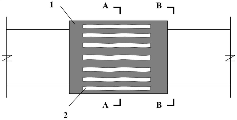
[0034] The invention provides a split wire sub-gap oscillation suppressing device, such as figure 1 The shown includes: two or more bushings 1;

[0035] The casing 1 is a hollow cylindrical structure, and a plurality of strip holes 2 are arranged on its side wall;

[0036] Each bushing 1 is installed side by side in the middle of different split conductors. At the same time, multiple bushings 1 are arranged perpendicular to the disaster wind direction and installed on multiple split conductors. When a wind disaster strikes, the airflow passes through multiple bushing, change the wake flow field of the wire, and change the original excitation conditions of the sub-gap oscillation of the wire at the same time, such as figure 2 As shown, the general disaster wind direction is along the horizontal direction, so for the four-split conductor, it can be installed on the upper two split conductors, or on the lower two split conductors, so that the horizontal wind can pass through th...

Embodiment 2

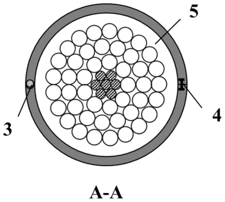
[0070] A sub-gauge vibration suppressing device for split conductors, including several sections of cylindrical open strip holes 2 sleeves 1, each section of sleeve is divided into two symmetrical halves in the radial direction, which are respectively connected by concealed buckles to form independent complete sleeves .

[0071] Several sections of bushings are arranged symmetrically in the middle of the sub-conductor where sub-gauge oscillation occurs.

[0072] The two halves of each section of casing are connected by a hinge 3 at one end, which can rotate along the axial direction of the sub-conductor; the other end is connected by a concealed buckle 4, and can be opened and closed.

[0073] The diameter of the cross-section of the bushing should be such that under the action of the average wind resistance and the electromagnetic attraction force generated by the normal current, there is no contact between the collars.

[0074] The gap 5 between the sleeve and the wire shou...


PUM


Abstract

The invention provides a split conductor subspan oscillation suppression device. The split conductor subspan oscillation suppression device comprises at least two sleeves (1), wherein each sleeve (1)is of a hollow cylinder structure, and a plurality of strip-shaped holes (2) are formed in the side wall of each hollow cylinder; the at least two sleeves (1) are arranged on different split conductors side by side; the air flow passes through the strip-shaped holes (2) of the plurality of sleeves (1), then the wake flow field of the conductor is changed, the original excitation condition of subspan oscillation of the conductor is changed at the same time, and subspan oscillation of the split conductor is restrained or weakened. The structure is simple, the installation is convenient and fast,and safe power supply is guaranteed.

Description

technical field [0001] The invention relates to the technical field of vibration control, in particular to a sub-gauge vibration suppression device for split conductors. Background technique [0002] Subconductor Oscillation / Wake Galloping is the phenomenon of conductor oscillation between two adjacent spacers at a certain wind speed (7-20m / s) on the transmission line of the phase-split conductor. It is called in structural wind engineering. It is the wake relaxation vibration, which is the vibration formed by the aerodynamic instability caused by the shear flow. The amplitude is about 3 to 20 times the diameter of the conductor, and the frequency is about 0.5 to 3 Hz, which is between breeze vibration and dancing, and the oscillation track is horizontal and flat oval. The sub-gap oscillation will cause the sub-conductors to collide and whip each other, wear the conductors, and the large amplitude will also increase the dynamic bending strain of the conductors at the spacer...

Claims


Application Information

Patent Timeline
Patent Type & Authority Applications(China)
IPC IPC(8): H02G7/14F15D1/00
CPCF15D1/0055H02G7/14
Inventor 刘彬李丹煜程永锋李鹏展雪萍
Owner CHINA ELECTRIC POWER RES INST
Learn More