Deicing device for high-voltage line

A high-voltage line and left box technology, applied in the field of high-voltage line deicing devices, can solve the problems of high-voltage line icing and deicing difficulties, and achieve the effects of improving deicing efficiency, reducing work intensity, and avoiding manual operation.

Active Publication Date: 2020-09-22
DEZHOU POWER SUPPLY COMPANY OF STATE GRID SHANDONG ELECTRIC POWER
View PDF6 Cites 0 Cited by
  • Summary
  • Abstract
  • Description
  • Claims
  • Application Information

AI Technical Summary

Problems solved by technology

[0005] Aiming at the deficiencies of the prior art, the present invention provides a deicing device for high-voltage lines, which solves the problem of difficult deicing of high-voltage lines

Method used


Image

  • Deicing device for high-voltage line
  • Deicing device for high-voltage line
  • Deicing device for high-voltage line

Examples


Embodiment 1

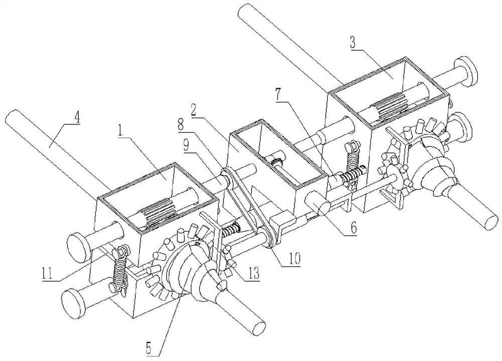
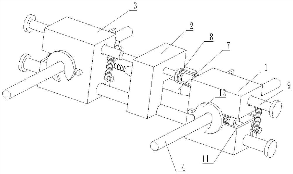
[0033] A deicing device for high voltage lines, such as Figure 1-Figure 5 As shown, it includes a left box body 1, which is characterized in that: the inside of the left box body 1 is slidably connected with two slide bars 9, the surface of the slide bar 9 is welded with a control box 2, and the inside of the control box 2 is provided with a drive mechanism 6, The surface of the slide bar 9 is slidably connected with the right box body 3, and the front parts of the left box body 1 and the right box body 3 are all provided with a deicing mechanism 5, and the surfaces of the left box body 1 and the right box body 3 are all provided with opening grooves 11 A telescopic mechanism 7 is arranged between the left box body 1 and the right box body 3, the inside of the left box body 1 is slidably connected with a cable body 4, and the rear parts of the left box body 1 and the right box body 3 are all rotatably connected with a clamping plate 12, The front part of the left box body 1 i...

Embodiment 2

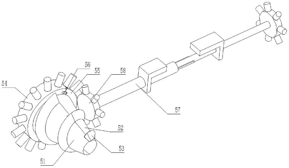
[0039] like Figure 6-7 As shown, the drive mechanism 6 includes a motor 61, the output end of the motor 61 runs through the inside of the control box 2 and is welded to the right end of the gear one 62, the surface of the gear one 62 is meshed with a gear two 63, and the inside of the gear two 63 is welded on the slide The surface of the bar 9 and the surface of the motor 61 are fixedly connected to the front portion of the control box 2 by bolts, the surface of the slide bar 9 is engaged with a scroll wheel 65, and the inside of the scroll wheel 65 is welded with a rotating shaft 64, and the surface of the rotating shaft 64 is connected in rotation. Inside the left case body 1 , a slide shaft 68 is slidably connected to the inside of the left case body 1 below the rotation shaft 64 .

[0040] In this embodiment, the inside of the left case 1 is slidably connected with a sliding shaft 68, and the surface of the sliding shaft 68 is welded with a sliding wheel 67, and the surfa...


PUM


Abstract

The invention relates to the technical field of high-voltage line maintenance. The invention further discloses a deicing device for ahigh-voltage line. The device comprises a left box body, two sliding rods are connected into the left box body in a sliding manner; a control box is welded to the surfacesof the sliding rods. A driving mechanism is arranged in the control box, a right box body is slidably connected to the surface of the sliding rod, deicing mechanisms are arranged on the front portions of the left box body and the right box body correspondingly, open grooves are formed in the surfaces of the left box body and the right box body correspondingly, and a telescopic mechanism is arranged between the left box body and the right box body. According to the high-voltage line deicing device,the deicing mechanisms run to directly rotate, crush and remove ice bars on aline body, the effects of automatic rolling and automatic deicing are achieved, automation is achieved, the deicing efficiency of the whole high-voltage line is improved, the working intensity of operators is further reduced, meanwhile, deicing is conducted through equipment, manual operation is avoided, and the safety of the operators is improved.

Description

technical field [0001] The invention relates to the technical field of high-voltage line maintenance, in particular to a deicing device for high-voltage lines. Background technique [0002] High-voltage line icing refers to the phenomenon that raindrops condense on the transmission line after encountering cold air, and the cold rain turns into ice to encase the line. Line icing is a serious natural disaster in the power supply system. Icing will cause line towers to fail Topple and break under pressure, which can lead to the paralysis of the entire power grid and power outages. Severe icing makes the tower unable to support the weight and collapse. [0003] At present, many deicing methods are manually operated, because the length of high-voltage lines is relatively long. This traditional method not only wastes manpower, but also has low efficiency in the deicing process. At the same time, there is high-voltage electricity on high-voltage lines. There is no certain guarante...

Claims


Application Information

Patent Timeline
Patent Type & Authority Applications(China)
IPC IPC(8): H02G7/16H02G1/02
CPCH02G1/02H02G7/16
Inventor 付永良陈新华李哲张亮薛志伟苏冰王秀颐于吉利张志强刘宝明赵鹏孟庆丰任强
Owner DEZHOU POWER SUPPLY COMPANY OF STATE GRID SHANDONG ELECTRIC POWER
Why Eureka
Try Eureka