Deicing device for high voltage line
A high-voltage line and left box technology, which is applied in the field of deicing devices for high-voltage lines, can solve the problems of high-voltage line icing and deicing difficulties, and achieve the effects of improving deicing efficiency, reducing work intensity, and avoiding manual operations
- Summary
- Abstract
- Description
- Claims
- Application Information
AI Technical Summary
Problems solved by technology
Method used
Image
Examples
Embodiment 1
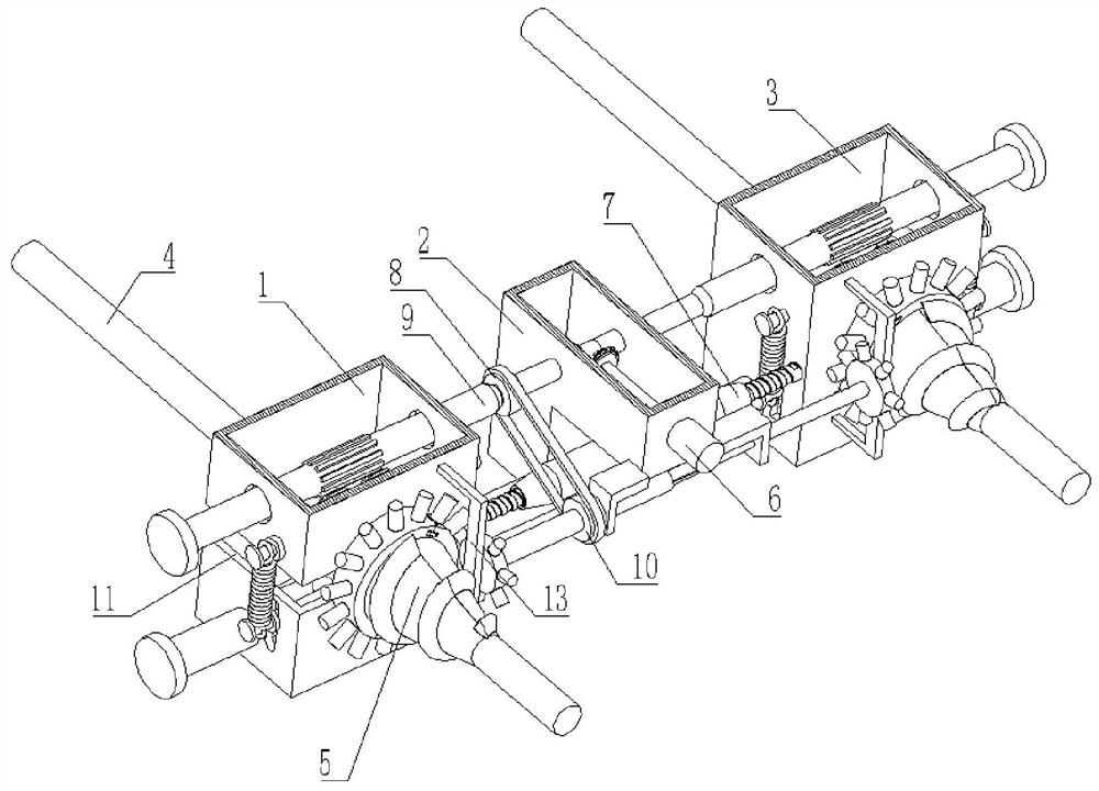
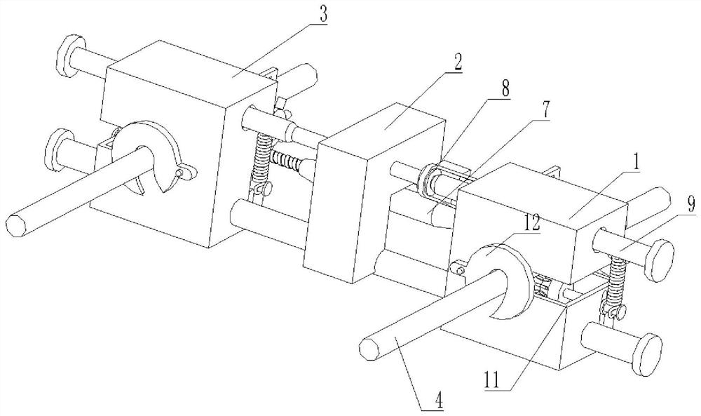
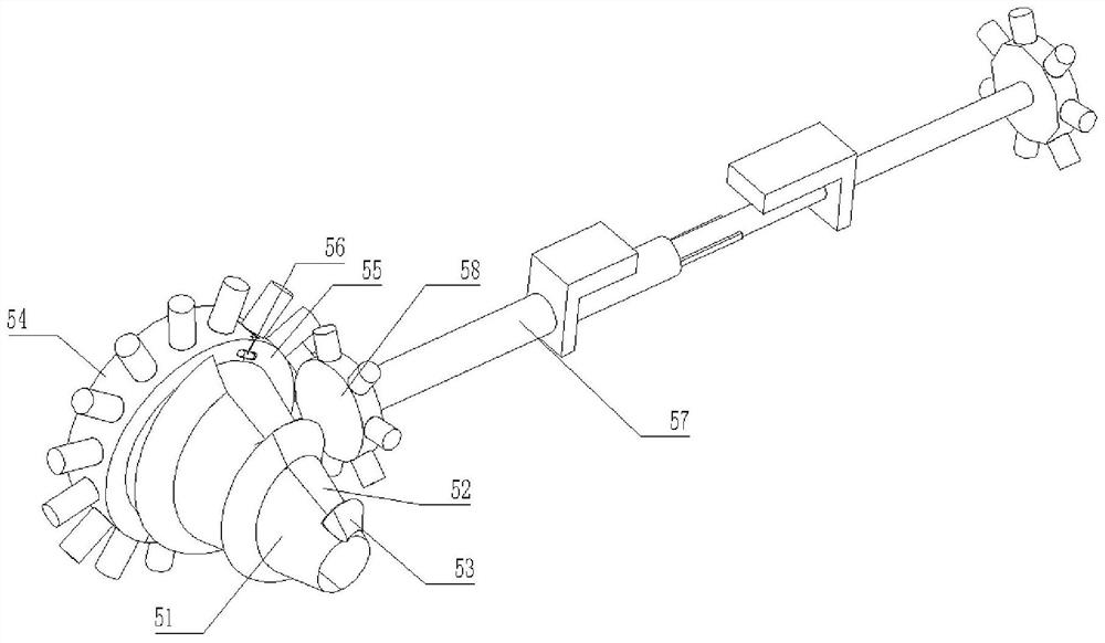
[0033] A deicing device for high voltage lines, such as Figure 1-Figure 5 As shown, it includes a left box body 1, which is characterized in that: the inside of the left box body 1 is slidably connected with two slide bars 9, the surface of the slide bar 9 is welded with a control box 2, and the inside of the control box 2 is provided with a drive mechanism 6, The surface of the slide bar 9 is slidably connected with the right box body 3, and the front parts of the left box body 1 and the right box body 3 are all provided with a deicing mechanism 5, and the surfaces of the left box body 1 and the right box body 3 are all provided with opening grooves 11 A telescopic mechanism 7 is arranged between the left box body 1 and the right box body 3, the inside of the left box body 1 is slidably connected with a cable body 4, and the rear parts of the left box body 1 and the right box body 3 are all rotatably connected with a clamping plate 12, The front part of the left box body 1 i...
Embodiment 2
[0039] Such as Figure 6-7 As shown, the drive mechanism 6 includes a motor 61, the output end of the motor 61 runs through the inside of the control box 2 and is welded to the right end of the gear one 62, the surface of the gear one 62 is meshed with a gear two 63, and the inside of the gear two 63 is welded on the slide The surface of the bar 9 and the surface of the motor 61 are fixedly connected to the front portion of the control box 2 by bolts, the surface of the slide bar 9 is engaged with a scroll wheel 65, and the inside of the scroll wheel 65 is welded with a rotating shaft 64, and the surface of the rotating shaft 64 is connected in rotation. Inside the left case body 1 , a slide shaft 68 is slidably connected to the inside of the left case body 1 below the rotation shaft 64 .
[0040] In this embodiment, the inside of the left case 1 is slidably connected with a sliding shaft 68, and the surface of the sliding shaft 68 is welded with a sliding wheel 67, and the su...
PUM
 Abstract
Description
Claims
Application Information
 - R&D
- Intellectual Property
- Life Sciences
- Materials
- Tech Scout
- Unparalleled Data Quality
- Higher Quality Content
- 60% Fewer Hallucinations
Browse by: Latest US Patents, China's latest patents, Technical Efficacy Thesaurus, Application Domain, Technology Topic, Popular Technical Reports.
© 2025 PatSnap. All rights reserved.Legal|Privacy policy|Modern Slavery Act Transparency Statement|Sitemap|About US| Contact US: help@patsnap.com


