Assembled cervical vertebra and unciform joint fusion cage

A modular, cage technology, applied in medical science, prostheses, spinal implants, etc., can solve the problems of high difficulty in installation and implantation, difficult implantation installation, lack of activity, etc. Effects of bone fusion and postoperative rehabilitation, reduction of prestressed load conditions, and convenient operation of implant assembly

Active Publication Date: 2020-09-25
WEST CHINA HOSPITAL SICHUAN UNIV
View PDF7 Cites 6 Cited by
  • Summary
  • Abstract
  • Description
  • Claims
  • Application Information

AI Technical Summary

Problems solved by technology

[0006] First, the elastic support body between the vertebral bodies and the fusion parts of the hook vertebral joints on both sides adopt an integrated structure design, resulting in the irregular joint space between the vertebral bodies during the implantation process, resulting in the elastic support body between the vertebral bodies and the joints on both sides It is difficult to implant and install the hook vertebral joint fusion components at the same time, so the installation and implantation operation is difficult;
[0007] Second, because the joint space of the hook vertebra is irregular, and the original joint fusion component of the hook vertebra is a single height-invariable structure, on the one hand, it is difficult to implant and install; The bone surface of the body is completely attached, which affects the postoperative recovery effect;
[0008] Third, the intervertebral elastic support body and the hook vertebra joint fusion components on both sides adopt an integrated structure design, but in actual conditions, the stress distribution between the intervertebral elastic support body and the lateral hook vertebra joint fusion components is inconsistent, so the operation Stress concentration often exists when the patient’s neck moves. Therefore, if the elastic support body between the vertebral bodies and the fusion components of the hook vertebra joints on both sides cannot effectively move relative to each other, the stress will not be distributed in various areas of the fusion cage, which will affect Patient Bone Graft Healing and Rehabilitation
[0009] Fourth, the elastic support body between the vertebral bodies is directly connected to the upper and lower vertebral bodies by screws, which lacks the necessary amount of activity, and there is a risk of stress concentration that may cause complications such as screw withdrawal, breakage, and bone resorption around the screw; at the same time, due to the lack of necessary The amount of activity leads to the lack of stress stimulation caused by micro-movement at the hook vertebral joint, which is not conducive to bone graft fusion and postoperative rehabilitation of patients

Method used


Image

  • Assembled cervical vertebra and unciform joint fusion cage
  • Assembled cervical vertebra and unciform joint fusion cage
  • Assembled cervical vertebra and unciform joint fusion cage

Examples


Embodiment Construction

[0058] The present invention will be further described below in conjunction with the accompanying drawings and specific embodiments.

[0059] It should be noted that if there are directional indications used in the present invention, such as up, down, left, right, front, back, direction and orientation terms, it is to facilitate the description of the relative positional relationship between components, not for related components and components. The absolute position of the positional relationship refers only to explaining the relative positional relationship and movement conditions between the components in a specific posture. If the specific posture changes, the directional indication will also change accordingly. .

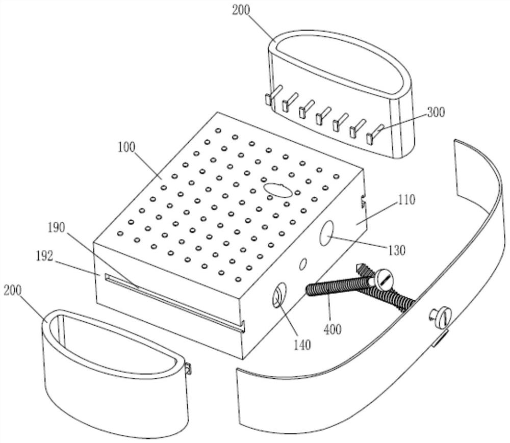
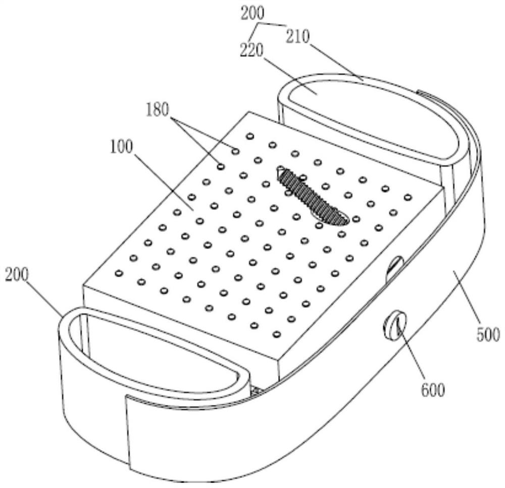
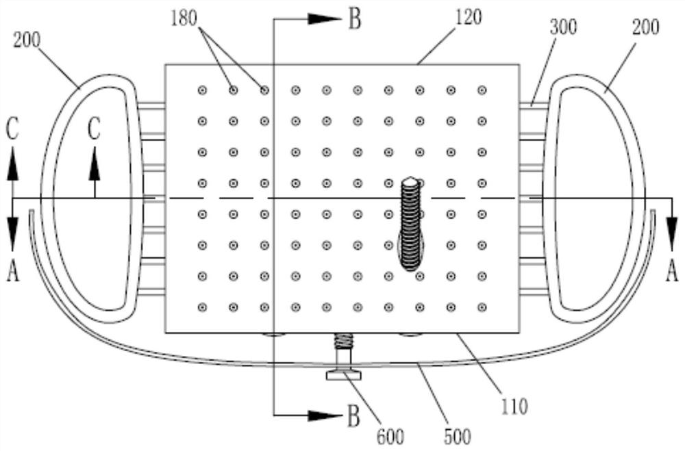
[0060] Such as Figure 1 to Figure 18 As shown in , the combined cervical vertebral hook vertebral joint fusion device of the present invention includes an intervertebral support body 100 and a hook vertebral joint fusion component 200. The hook vertebral join...


PUM


Abstract

The invention discloses an assembled cervical vertebra and unciform joint fusion cage, belongs to the field of medical instruments, and provides an assembled cervical vertebra and unciform joint fusion cage which is more convenient to implant and install. The assembled cervical vertebra and unciform joint fusion cage comprises an intervertebral support body and unciform joint fusion components, wherein each unciform joint fusion component comprises a circle of cofferdam; a bone grafting cavity which is through up and down is formed in the cofferdam; the unciform joint fusion components are correspondingly arranged on the left side and the right side of the intervertebral support body; the assembled cervical vertebra and unciform joint fusion cage further comprises a connecting piece; the intervertebral support body and the unciform joint fusion components are arranged in a split manner; and the intervertebral support body and the unciform joint fusion components can be assembled and installed through the connecting piece. According to the assembled cervical vertebra and unciform joint fusion cage, through the arrangement of the split structure, the implantation and installation canbe carried out in sequence during implantation and installation, so that the problem that the implantation is difficult due to the fact that the implantation is carried out at the same time when theintegrated structure is arranged is avoided. In addition, through the arrangement of the deformable cofferdam, the implantation and installation operation can be facilitated, the fitting effect is improved, and meanwhile, the early osteogenic fusion is facilitated.

Description

technical field [0001] The invention relates to the field of medical instruments, in particular to an assembled cervical hook-vertebral joint fusion device. Background technique [0002] Anterior cervical decompression and fusion (ACDF) has always been an effective and classic surgical method for the treatment of cervical degenerative diseases. Anterior cervical plate, cervical intervertebral fusion device and other implant materials can improve the initial stability, support strength and bone graft fusion rate of ACDF surgery. Among them, the basic purpose of the design of the cervical intervertebral fusion device is to maintain and improve the curvature of the cervical spine on the basis of providing good initial stability and support strength, and to provide a good biological and biomechanical environment for intervertebral fusion to promote bone grafting. fusion. [0003] There are many types of cervical fusion cages on the market, but the basic design is still a cylin...

Claims


Application Information

Patent Timeline
Patent Type & Authority Applications(China)
IPC IPC(8): A61F2/44
CPCA61F2/4455A61F2220/0025A61F2002/448A61F2250/0058
Inventor 刘浩杨毅洪瑛丁琛王贝宇孟阳
Owner WEST CHINA HOSPITAL SICHUAN UNIV
Why Eureka
Try Eureka