
Mechanical seal assembly capable of measuring internal pressure for carbon steel reaction kettle

A technology of mechanical seals and reactors, which is applied in chemical/physical/physicochemical fixed reactors, sound-generating devices, fixed filter elements, etc., can solve the problem that the pressure of carbon steel reactors cannot be accurately monitored and contains large Impurities and other problems, to achieve the effect of easy handling, simple operation and easy cleaning

Inactive Publication Date: 2020-09-25
JIANGSU YITONG FLUID TECH
View PDF7 Cites 1 Cited by
  • Summary
  • Abstract
  • Description
  • Claims
  • Application Information

AI Technical Summary

Problems solved by technology

[0004] The purpose of the present invention is to provide a mechanical seal assembly for a carbon steel reactor that can measure the internal pressure, so as to solve the problem that the existing existing carbon steel reactor proposed in the above background technology has problems such as pressure measuring tubes and carbon seals when working. There is a gap at the joint of the steel reactor, the pressure of the entire carbon steel reactor cannot be accurately monitored, the motor on the upper side of the carbon steel reactor does not deal with the noise when it is working, and the heating oil in the oil storage tank is recycled for a long time. Problems with a lot of impurities

Method used


Image

  • Mechanical seal assembly capable of measuring internal pressure for carbon steel reaction kettle
  • Mechanical seal assembly capable of measuring internal pressure for carbon steel reaction kettle
  • Mechanical seal assembly capable of measuring internal pressure for carbon steel reaction kettle

Examples


Embodiment Construction

[0027] The technical solutions in the embodiments of the present invention will be clearly and completely described below in conjunction with the accompanying drawings in the embodiments of the present invention. Obviously, the described embodiments are only a part of the embodiments of the present invention, rather than all the embodiments. Based on the embodiments of the present invention, all other embodiments obtained by those of ordinary skill in the art without creative work shall fall within the protection scope of the present invention.

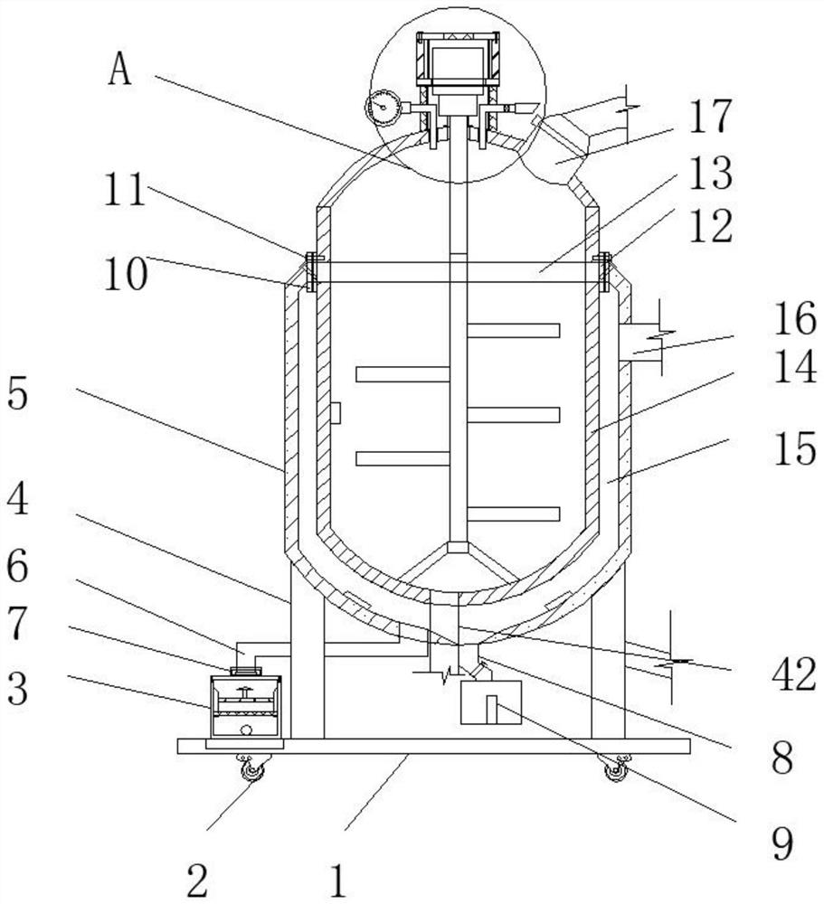
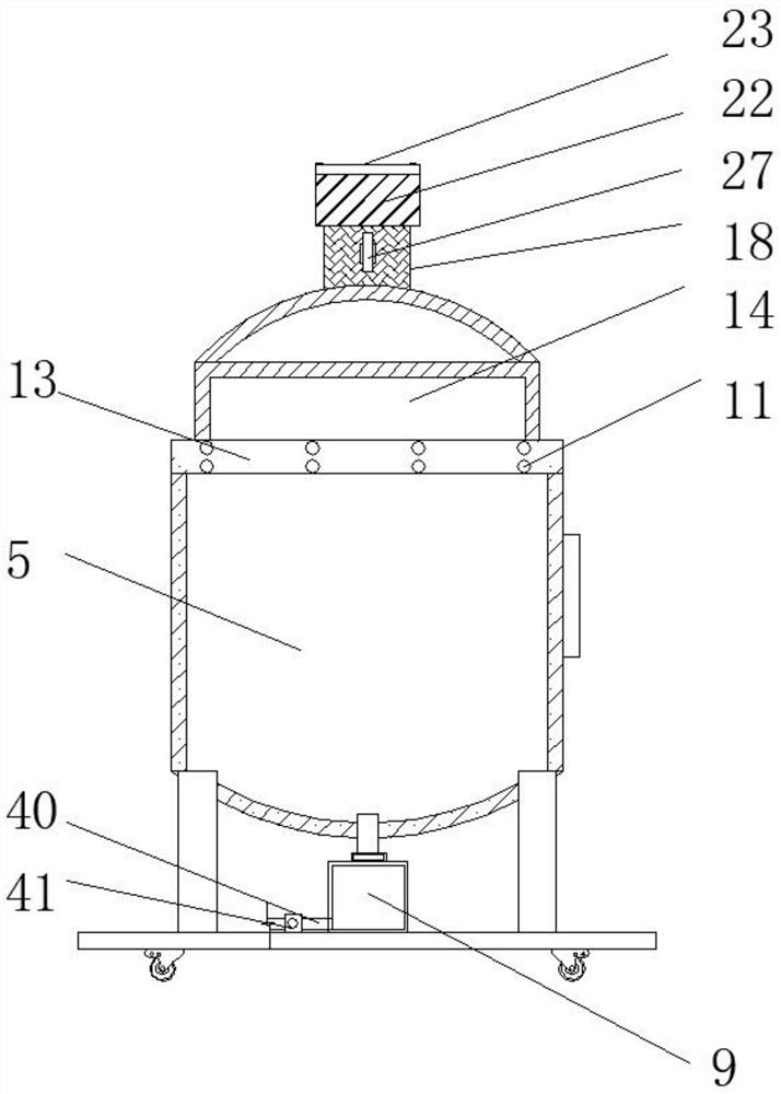
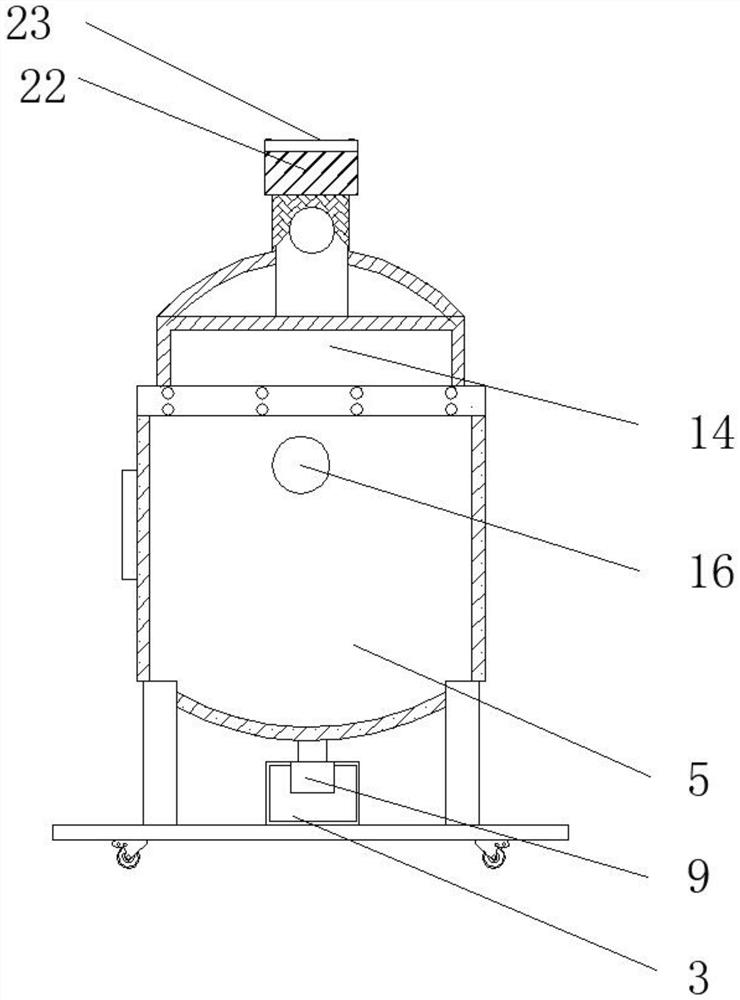
[0028] See Figure 1-7 , The present invention provides a technical solution: a mechanical seal assembly for carbon steel reactor that can measure internal pressure, such as figure 1 , figure 2 with Image 6 As shown, the lower side of the bottom plate 1 is fixed with a self-locking roller 2, and the upper side of the bottom plate 1 is provided with a filter assembly 3 and a support rod 4, while the right side of the filter assembly 3 is...


PUM


Abstract

The invention discloses a mechanical seal assembly capable of measuring internal pressure for a carbon steel reaction kettle. The mechanical seal assembly comprises a bottom plate and a control box, wherein self-locking rollers are fixed on the lower side of the bottom plate; a first carbon steel reaction kettle shell is fixed on the upper side of the support rod; the lower side of the oil conveying pipe is in threaded connection with a filtering assembly through a hollow threaded fixing piece; a material guiding pipe is arranged on the right side of the oil conveying pipe, a first fixing plate is fixed to the inner wall of the upper side of the first carbon steel reaction kettle shell, a second carbon steel reaction kettle shell is fixed to the inner wall of the annular fixing plate, anda feeding port penetrates through the right end of the upper side of the second carbon steel reaction kettle shell. According to the mechanical sealing assembly capable of measuring the internal pressure for the carbon steel reaction kettle, the sealing assembly is arranged, and the sealing box, the sealing strip and the first sealing ring in the sealing assembly interact with one another to perform multi-layer sealing, so that the sealing pressure detection data are prevented from being influenced when the joints of the pressure measuring pipe, the pressure discharging pipe and the shell of the second carbon steel reaction kettle are not sealed thoroughly.

Description

Technical field [0001] The invention relates to the technical field of carbon steel reactors, in particular to a mechanical seal assembly capable of measuring internal pressure for carbon steel reactors. Background technique [0002] The broad understanding of the reactor is a container with physical or chemical reactions. Through the structural design and parameter configuration of the container, the heating, evaporation, cooling and low-speed mixing functions required by the process are realized. The reactor is widely used in petroleum, chemical, Rubber, pesticides, dyes, medicine and other fields. [0003] The existing existing carbon steel reactors are mostly sealed by sealing rings during work. For example, there is a gap at the connection between the pressure measuring tube and the carbon steel reactor, and the pressure of the entire carbon steel reactor cannot be accurately monitored. The processing quality of the carbon steel reactor. The motor on the upper side of the car...

Claims


Application Information

Patent Timeline
Patent Type & Authority Applications(China)
IPC IPC(8): B01J19/18B01J19/00B01D29/03B01D29/56B01D35/02B01D36/04G10K11/162
CPCB01D29/03B01D29/56B01D35/02B01D36/04B01J19/0006B01J19/0013B01J19/0053B01J19/0066B01J19/0073B01J19/18G10K11/162
Inventor 王杰夏伟夏欣龙
Owner JIANGSU YITONG FLUID TECH
Learn More