
Building sand screening device

A sand screener and construction technology, which is applied in the direction of filter screen, chemical instrument and method, solid separation, etc., can solve the problems of laborious screen screening, low screening efficiency, etc., and achieve the effect of preventing clogging, convenient screening, and convenient movement

Active Publication Date: 2020-09-25
廖秀红
View PDF8 Cites 4 Cited by
  • Summary
  • Abstract
  • Description
  • Claims
  • Application Information

AI Technical Summary

Problems solved by technology

[0004] In order to overcome the shortcomings of laborious and laborious screening by manual use of screening nets and low screening efficiency, the technical problem of the present invention is to provide a construction sand screen that is easy to move and quickly screen

Method used


Image

  • Building sand screening device
  • Building sand screening device
  • Building sand screening device

Examples


Embodiment 1

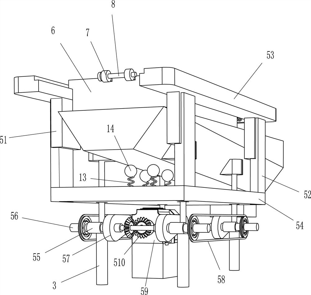
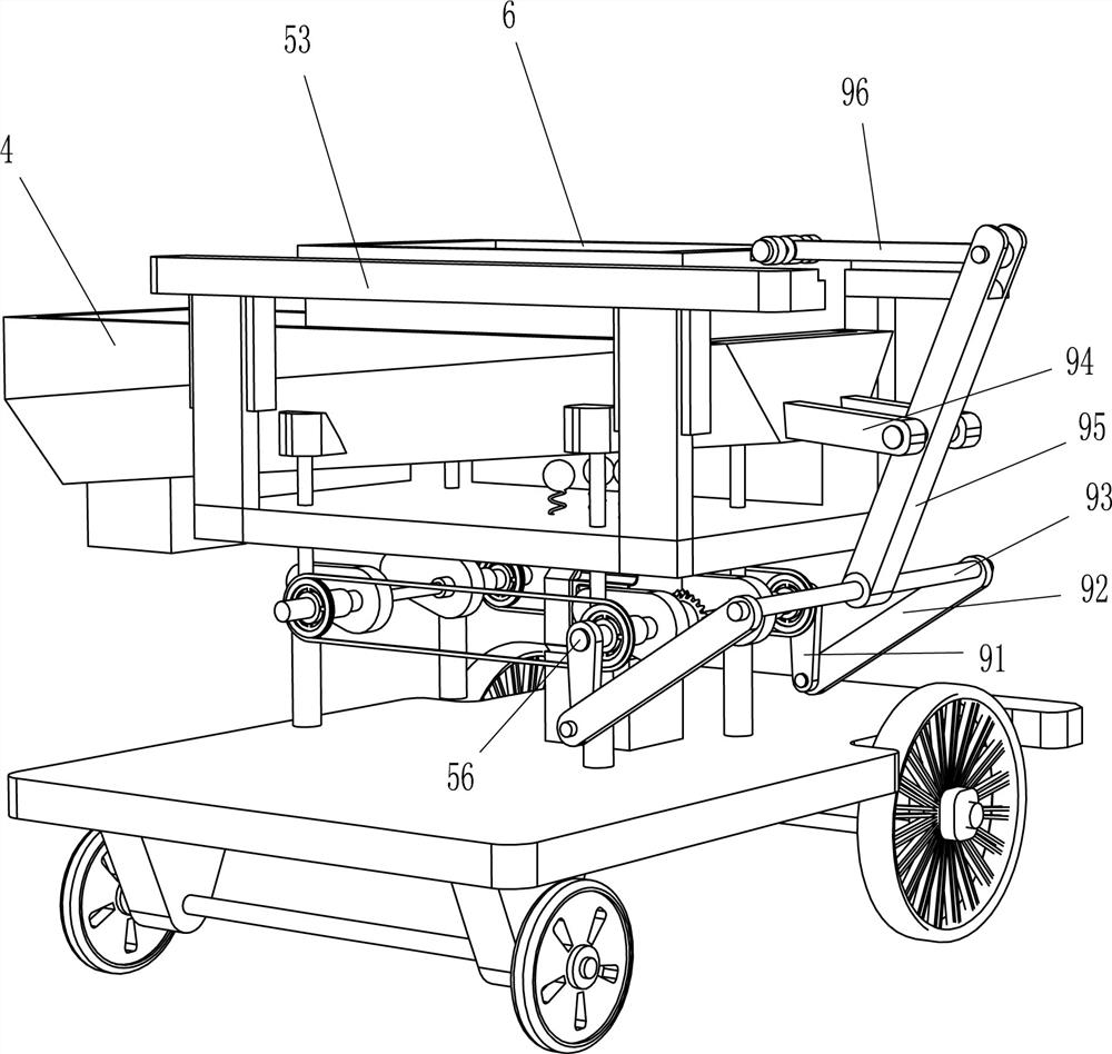
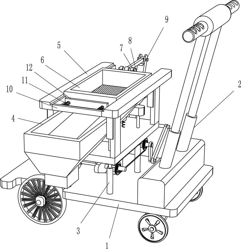
[0020] A building sand sieve, such as Figure 1-3 As shown, it includes vehicle frame 1, push rod 2, guide column 3, drop hopper 4, up and down vibration mechanism 5, screening frame 6, inserting sleeve 7, inserting rod 8 and swing mechanism 9, and the right side of the top of vehicle frame 1 is provided with The push rod 2 and the top of the vehicle frame 1 are provided with 4 guide columns 3 connected by bolts, and the 4 guide columns 3 are combined into a rectangular arrangement. The upper and lower vibrating mechanisms 5 are provided, and the upper and lower vibrating mechanisms 5 are slidingly provided with a screening frame 6. The screening frame 6 is located directly above the falling hopper 4. The left and right side walls of the screening frame 6 are symmetrically arranged with a plug sleeve 7 by welding, and the plug sleeve The plug-in type in 7 is provided with inserting rod 8, and up and down vibrating mechanism 5 is provided with the swing mechanism 9 that screen ...

Embodiment 2

[0025] On the basis of Example 1, such as Figure 1-2 As shown, it also includes a baffle plate 10, a first elastic member 11 and a buffer plate 12, a baffle plate 10 is connected between the front ends of the two slide rails 53, the rear side of the baffle plate 10 is uniformly provided with a first elastic member 11, the first elastic The member 11 is a compression spring, and the rear end of the first elastic member 11 is provided with a buffer plate 12 . The swing rod 95 drives the screening frame 6 to move back and forth on the slide rail 53 through the second connecting rod 96, and then realizes the back and forth movement of the screening frame 6. The screening frame 6 squeezes the buffer plate 12, which can play the vibration of the screening frame 6 and prevent The screen frame at the bottom of the screening frame 6 is blocked, and the first elastic member 11 plays a buffering role on the buffer plate 12 .

[0026] It also includes a second elastic piece 13 and a kno...


PUM


Abstract

The invention belongs to the technical field of building processing equipment, and particularly relates to a building sand screening device. The technical problem is how to provide the building sand screening device which is convenient to move and realizes rapid screening. The building sand screening device comprises a trolley frame, guide columns, a dropping hopper, an up-down vibrating mechanism, a screening frame, insertion sleeves, insertion rods and a swing mechanism, wherein the four guide columns are arranged at the top of the trolley frame and combined into a rectangle, the dropping hopper is arranged at the tops of the four guide columns, the up-down vibrating mechanism is arranged on the four guide columns, the screening frame is arranged on the up-down vibrating mechanism and located over the dropping hopper, the insertion sleeves are symmetrically arranged on one side wall of the screening frame, the insertion rods are arranged in the insertion sleeves in an inserted manner, and the up-down vibrating mechanism is provided with the swing mechanism for shaking the screening frame horizontally. The building sand screening device achieves the effects of being convenient tomove and realizing rapid screening.

Description

technical field [0001] The invention belongs to the technical field of construction processing equipment, in particular to a construction sand screen. Background technique [0002] At the construction site, sand is an essential basic raw material in the construction field. There are many impurities in the sand, such as gravel, garbage, etc., and the sand in the sand is also divided into different grades, with different uses. Sand comes in different particle size classes. Therefore, it is necessary to sieve the sand before using it. Most of the commonly used drum sand screening machines are straight cylinder design. The larger sand particles screened out tend to accumulate in the drum and cannot be automatically discharged. Moreover, the drum is not easy to disassemble and the cleaning is cumbersome. Moreover, the overall structure of the sand screening machine is single, and the sand is classified. The effect is poor. [0003] The fine sand that needs to be used in the pr...

Claims


Application Information

Patent Timeline
Patent Type & Authority Applications(China)
IPC IPC(8): B07B1/36B07B1/46
CPCB07B1/36B07B1/005B07B1/46
Inventor 廖秀红
Owner 廖秀红
Learn More