Electric industrial brush device convenient to adjust

An industrial and electric technology, used in grinding drives, grinding/polishing safety devices, manufacturing tools, etc., can solve problems such as low use efficiency and poor adjustment effect, and achieve the effect of improving efficiency, preventing residues and facilitating cleaning

Inactive Publication Date: 2020-09-25
潜山卓越机电设备有限公司
View PDF8 Cites 7 Cited by
  • Summary
  • Abstract
  • Description
  • Claims
  • Application Information

AI Technical Summary

Problems solved by technology

[0004] The purpose of the present invention is to solve the problem of poor adjustment effect and low efficiency of the combined device of the industrial brush in the prior art, and propose an electric industrial brush device that is easy to adjust

Method used


Image

  • Electric industrial brush device convenient to adjust
  • Electric industrial brush device convenient to adjust
  • Electric industrial brush device convenient to adjust

Examples


Embodiment 1

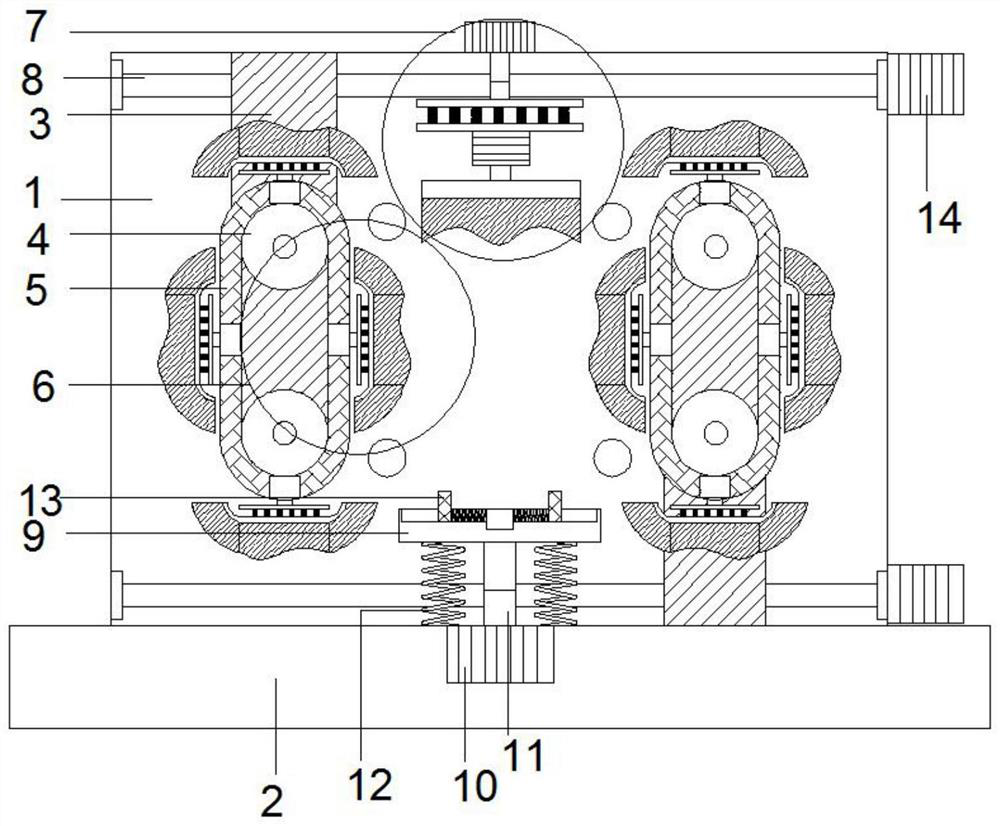
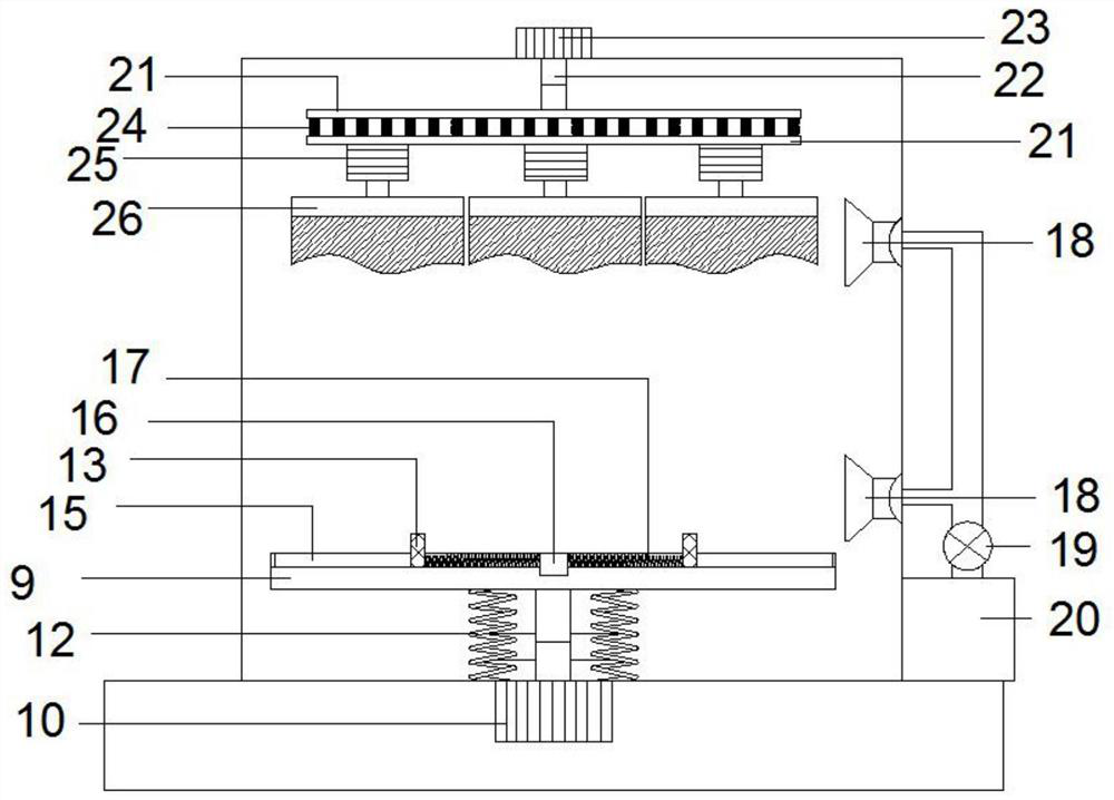
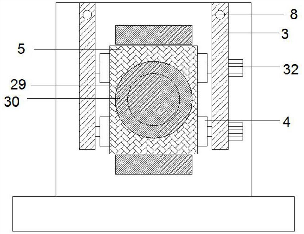
[0029] refer to Figure 1-6 , an electric industrial brush device that is easy to adjust, including a scrubbing box 1, a base 2 fixedly connected to the bottom of the scrubbing box 1, and a side cleaning mechanism 6 arranged symmetrically on the left and right sides inside the scrubbing box 1, and a set at the upper end of the scrubbing box 1 The top cleaning mechanism 7, the top cleaning mechanism 7 includes a second cylinder 23 arranged at the center of the top of the scrubbing box 1 and a second telescopic rod 22 connected to the lower end of the second cylinder 23, and the lower end of the second telescopic rod 22 extends to the scrubbing The inside of the box 1 is fixed to the connecting plate 21, and the lower end of the connecting plate 21 is fixedly connected to a plurality of second motors 25, the output shaft at the lower end of the second motor 25 is fixed to the cleaning brush 26 at the upper end, and the brushing box directly below the top cleaning mechanism 7 1 T...

Embodiment 2

[0036] Such as Figure 1-6As shown, this embodiment is basically the same as Embodiment 1. In order to facilitate the clamping of parts of different sizes, preferably, a center block 16 is arranged inside the center of the upper end of the bottom plate 9, and a center block 16 is provided on the bottom plate 9 around the center block 16. The chute 15 , the lower end of the side plate 13 is inserted into the chute 15 and is slidably connected with the bottom plate 9 , and the part of the side plate 13 inserted into the chute 15 is connected with the central block 16 through a connection spring 17 .

[0037] In order to improve the stability of the top cleaning mechanism 7, preferably, the lower end of the second telescopic rod 22 is connected to two layers of connecting plates 21, and the two layers of connecting plates 21 are connected by a plurality of second elastic members 24, and the lower end The connecting plate 21 is fixed to the second motor 25 .

[0038] Working prin...


PUM


Abstract

The invention discloses an electric industrial brush device convenient to adjust, and relates to the technical field of processing of industrial brushes. The electric industrial brush device comprisesa brushing box, a base, a side edge cleaning mechanism and a top cleaning mechanism; the top cleaning mechanism comprises a second air cylinder, a second telescopic rod, a connecting plate, a secondmotor and an upper-end cleaning brush; the side edge cleaning mechanism comprises a rotating shaft and a rotating track; multiple third motors are arranged inside the rotating track; output shafts ofthe third motors are fixed to side edge brushes; two pairs of reciprocating screws are symmetrically arranged at the upper and lower ends of the brushing box; the side edge cleaning mechanism is fixedthrough a sliding block; and two groups of spraying openings are symmetrically formed in the upper and lower ends of a back plate inside the brushing box. According to the electric industrial brush device, defects in the prior art are overcome, the device is reasonable in design and convenient to use, cleaning and rust removal can be effectively performed on parts in different sizes, meanwhile, the positions of the industrial brushes can be adjusted conveniently, and the cleaning efficiency can be improved.

Description

technical field [0001] The invention relates to the technical field of industrial brush processing, in particular to a conveniently adjustable electric industrial brush device. Background technique [0002] Industrial brushes are new products that are upgraded and improved on the basis of civilian brushes. They are mainly used for cleaning, dust removal, polishing, etc. in the process of industrial production. However, traditional industrial brushes are manually scrubbed, and the cleaning effect is not good. Strong. [0003] Due to the actual processing needs at this stage, it is often necessary to modify the surface of parts or objects of different materials and signals to remove dust and rust. Most of them use industrial brushes to assemble them into integrated devices. However, the existing industrial brush assembly devices often It can process a single type of parts, and the processing efficiency is low, it cannot be applied to the processing of most of the above parts,...

Claims


Application Information

Patent Timeline
Patent Type & Authority Applications(China)
IPC IPC(8): B08B1/00B08B1/04B08B3/02B08B13/00B24B27/00B24B27/033B24B41/02B24B41/04B24B41/06B24B47/04B24B47/12B24B47/22B24B55/06
CPCB08B1/002B08B1/04B08B3/02B08B13/00B24B27/033B24B27/0076B24B47/12B24B41/06B24B47/22B24B41/02B24B47/04B24B41/04B24B55/06
Inventor 徐礼红张菊霞
Owner 潜山卓越机电设备有限公司
Why Eureka
Try Eureka