Plate bending equipment

A technology of bending and plate body, which is applied in the field of plate processing, can solve the problems of reducing processing efficiency, affecting the appearance, reducing the thickness of the plate body, etc., and achieves the effect of improving service life, long service life and small sliding distance

Active Publication Date: 2020-09-25
CHONGQING COLLEGE OF ELECTRONICS ENG
View PDF6 Cites 1 Cited by
  • Summary
  • Abstract
  • Description
  • Claims
  • Application Information

AI Technical Summary

Problems solved by technology

However, the punch of the traditional bending machine usually moves in a straight line, that is, the movement track of the punch is perpendicular to the plane of the plate body. When the punch bends and deforms the plate body, the punch also needs to slide relative to the concave surface of the plate body. Squeeze or withdraw. At this time, due to the high pressure between the punch and the plate body, when the punch slides relative to the plate body, the contact between the plate body and the punch is easily subject to greater friction, and the surface of the plate body is easily damaged. scratch
After the board body is bent, it is usually used to process the shell of vehicles or other machines. In the case of deep scratches, after spray painting, the surface of the board body after painting is still uneven, which affects the appearance.
In order to make the shell more beautiful, it is usually necessary to polish the surface of the board after bending, but at the beginning of polishing, on the one hand, it is easy to further reduce the thickness of the board and reduce the strength of the board; on the other hand, it will increase Processing procedure, reduce processing efficiency

Method used


Image

  • Plate bending equipment
  • Plate bending equipment
  • Plate bending equipment

Examples


Embodiment 1

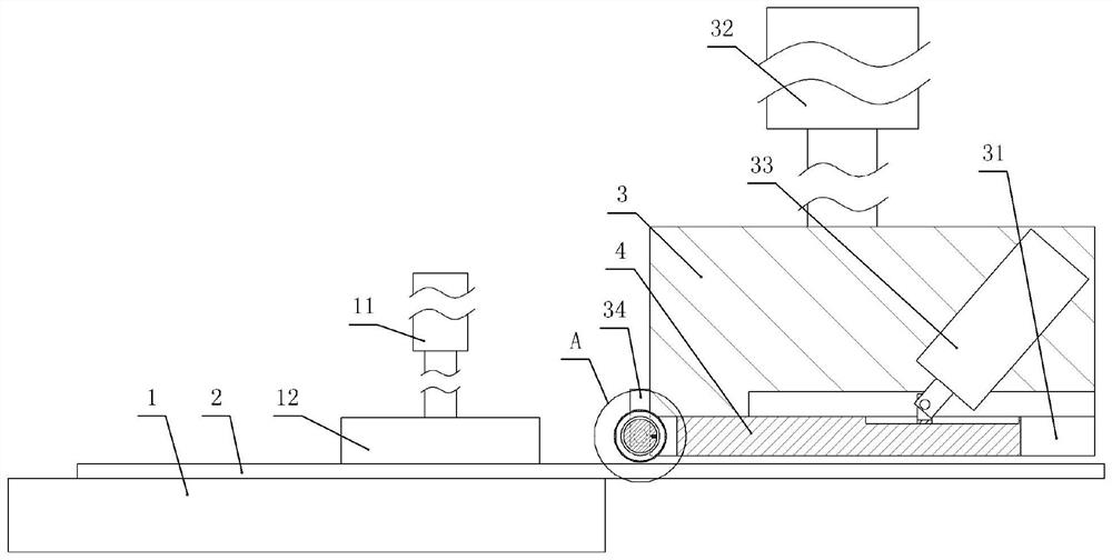
[0034] Plate bending equipment, such as figure 1 and figure 2 As shown, it includes frame, workbench 1, pressing unit, punch and first drive member 32, workbench 1 is welded on the frame horizontally, and press unit, punch and first drive member 32 are all located on the workbench 1, the compression unit includes a compression hydraulic cylinder 11 and a compression block 12, the compression hydraulic cylinder 11 is fixed on the frame by bolts and the push rod of the compression hydraulic cylinder 11 faces downward, and the compression block 12 is welded on the The push rod lower end of hydraulic cylinder 11.

[0035] The first driving part 32 and the vertical projection of the punch are all located on the right side of the workbench 1. The first driving part 32 in this embodiment adopts a hydraulic cylinder, and the first driving part 32 is fixed on the frame by bolts. The push rod of the first driving member 32 faces downward. The punch includes a main body 3 and a bendi...

Embodiment 2

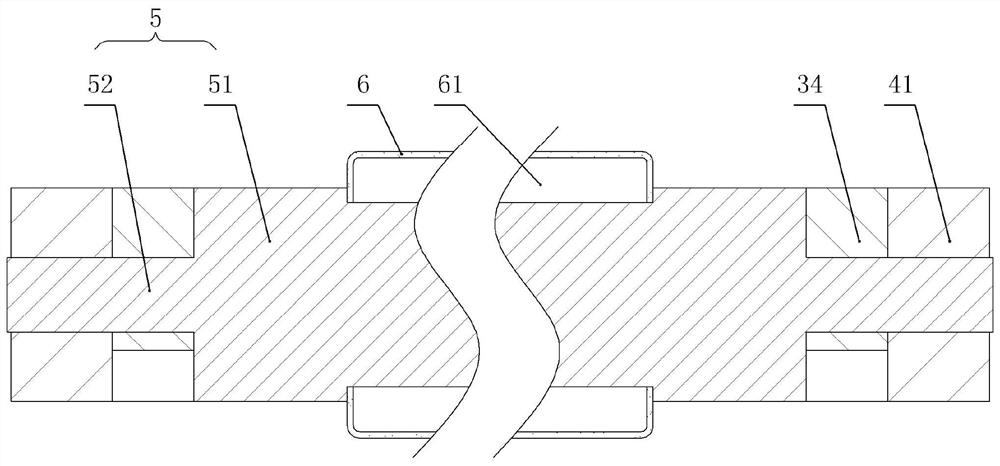
[0043] On the basis of Example 1, such as Figure 5 As shown, the bottom of the bent plate 4 in this embodiment is glued with a rubber layer made of rubber. In addition, the front end of the main body 3 is vertically welded with a plate-shaped angle measuring device 7, the lower end of the angle measuring device 7 is lower than the main body 3 and the angle measuring device 7 is located on the front side of the bending plate 4, and the angle measuring device 7 is provided with several measuring bends. The scale line of the rotation angle of the folding plate 4.

[0044] In this embodiment, after the bending plate 4 is rotated, the bending angle of the bending plate 4 is the same as the bending angle of the plate body 2 because the bending plate 4 sticks to the bent part of the plate body 2 . In this embodiment, when the bending plate 4 is rotated, when the bending plate 4 is aligned with the scale on the angle measuring device 7, the scale on the angle measuring device 7 is t...


PUM


Abstract

The invention relates to the field of plate machining, in particular to plate bending equipment. The plate bending equipment comprises a male die and a first driving part, wherein the male die comprises a body and a bending unit, one end of the body is connected with the first driving part, and the first driving part drives the body to slide; and the bending unit comprises a bending plate hinged to the end of the male die and a second driving piece driving the bending plate to rotate, the bending plate is located at the end, away from the driving piece, of the body, and the second driving piece is fixed to the body. According to the plate bending equipment, the plate can be prevented from being subjected to a large friction effect, so that the situation that the surface of the plate needsto be polished after being scratched, and the machining efficiency is reduced is avoided.

Description

technical field [0001] The invention relates to the field of plate processing, in particular to a plate body bending equipment. Background technique [0002] The current means of transportation such as vehicles or other machinery contain curved plates. During processing, the thin plates with small thickness are usually processed first, and then the thin plates are cut into plates according to the required size, and then bent. The machine processes the plate body to make the plate body bend at a certain angle. [0003] The current bending machine usually includes a punch and a driving part. During processing, the driving part drives the punch to move to the side close to the plate body, and then exerts pressure on the plate body to cause the plate body to bend and deform. However, the punch of the traditional bending machine usually moves in a straight line, that is, the movement track of the punch is perpendicular to the plane of the plate body. When the punch bends and def...

Claims


Application Information

Patent Timeline
Patent Type & Authority Applications(China)
IPC IPC(8): B21D5/04B21D5/00
CPCB21D5/04B21D5/002B21D5/006
Inventor 叶勇朱游兵
Owner CHONGQING COLLEGE OF ELECTRONICS ENG
Why Eureka
Try Eureka