
Novel automatic plate shearing machine

A shearing machine and automatic technology, applied in the direction of shearing machine equipment, shearing devices, shearing machine accessories, etc., can solve the problems of time-consuming, equipment troublesome, manpower consumption, etc., to save manpower and production time, save space Effects of travel time and productivity improvement

Active Publication Date: 2020-09-25
江苏创恒机械科技有限公司
View PDF6 Cites 4 Cited by
  • Summary
  • Abstract
  • Description
  • Claims
  • Application Information

AI Technical Summary

Problems solved by technology

If it is necessary to continuously cut materials with the same width, the above method is time-consuming, manpower-consuming, and inefficient; at the same time, due to the need for workers' auxiliary operations, there will be some possibility of endangering the personal safety of workers
[0004] In addition, the publication number CN108405952B discloses a plate shearing machine, which can realize automatic and continuous shearing of plates, but when adjusting the width of the sheared plates, it is necessary to replace the number of teeth of the driving gear and the driven gear. This method is very laborious for the equipment

Method used


Image

  • Novel automatic plate shearing machine
  • Novel automatic plate shearing machine
  • Novel automatic plate shearing machine

Examples


Embodiment Construction

[0039] Attached below Figure 1-11 The present invention is described in detail below.

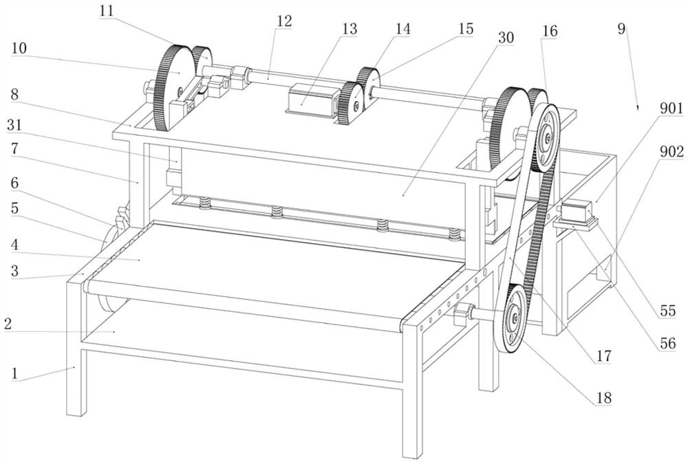
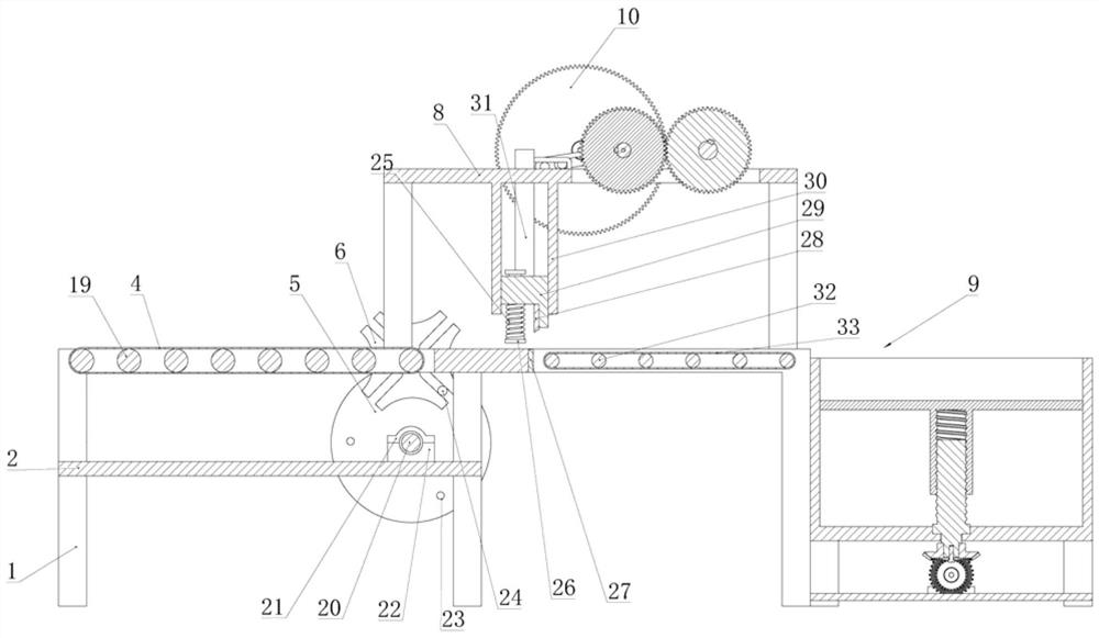
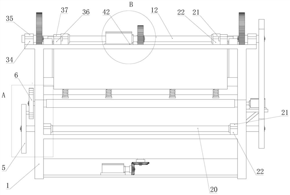
[0040] A new type of automatic shearing machine, see attached Figure 1-11 , comprising a lower column 1, a base 3, a lower cutter 27, and an upper cutter 28, the four corners of the lower end of the base 3 and the middle positions of the sides are welded with six lower columns 1 perpendicular to the plane of the base 3, the bottom of the base 3 And between the four lower columns 1 located at the front ends, a lower bottom plate 2 parallel to the plane of the base 3 is welded. Two lower bearing bushes 22 are respectively bolted on the left and right sides of the upper top surface of the lower bottom plate 2. The upper bearing bush 1 21 is bolt-connected at the position of the coaxial line above the lower bearing bush 1 22, and a freely rotatable small pulley rotating shaft 20 is installed at the coaxial position between the lower bearing bush 1 22 and the upper bearing bush 1 21. A small...


PUM

PropertyMeasurementUnit
widthaaaaaaaaaa
widthaaaaaaaaaa
lengthaaaaaaaaaa

Abstract

The invention discloses a novel automatic plate shearing machine. The novel automatic plate shearing machine comprises lower stand columns, a base, a lower cutter and an upper cutter, the lower standcolumns are welded to the lower portion of the base, a lower bottom plate is welded between the lower stand columns, the upper portion of the base is connected with upper stand columns, an upper top plate is arranged above the upper stand columns, a mechanism used for cutting is arranged on the upper top plate, a feeding roller and a feeding belt are arranged on the front half portion of the base,a discharging roller and a discharging belt are arranged on the rear half portion of the base, the lower cutter is mounted in the middle of the base, a sheave mechanism is arranged at the left end ofthe base, a large pulley, a small pulley and a synchronous conveying belt are arranged at the right end of the base, and a receiving device is arranged behind the base. According to the design scheme, automatic cutting production of the equal-width plates is achieved, manpower and production time are greatly saved, production efficiency is improved, the width of the sheared plates is convenientlyadjusted, workpieces can be prevented from being damaged due to large impact during material receiving, and the advantages of being stable in transmission process and cutting process and the like areachieved.

Description

technical field [0001] The invention relates to the technical field of plate processing equipment, in particular to a novel automatic plate shearing machine. Background technique [0002] The shearing machine is a machine that uses one blade to make a reciprocating linear motion relative to the other blade to cut the plate. It uses the moving upper blade and the fixed lower blade to apply shearing force to metal sheets of various thicknesses with a reasonable blade gap, so that the sheets are broken and separated according to the required size. Shearing machine is a kind of forging machinery, mainly used in metal processing industry. [0003] So far, most of the shearing machines use manual feeding, requiring workers to place the plate in the designated position, and then control the machine to cut. After the cutting is completed, the worker needs to take the cut material out of the machine. . If it is necessary to continuously cut materials with the same width, the above...

Claims


Application Information

Patent Timeline
Patent Type & Authority Applications(China)
IPC IPC(8): B23D15/08B23D15/12B23D33/02
CPCB23D15/08B23D15/12B23D33/02
Inventor 刘宝林
Owner 江苏创恒机械科技有限公司
Learn More