
Polishing device for inner wall of satellite antenna panel

A satellite antenna and polishing device technology, which is applied to surface polishing machine tools, grinding drive devices, grinding/polishing equipment, etc., can solve the problem of poor smoothness of the inner wall of the antenna panel, which cannot meet the needs of mass production and polishing efficiency. Low-level problems, to achieve the effect of wide application range, strong practicability, and high polishing efficiency

Active Publication Date: 2020-09-25
CHENGDU ANDI XINGYU ELECTRONICS SCI & TECH
View PDF14 Cites 0 Cited by
  • Summary
  • Abstract
  • Description
  • Claims
  • Application Information

AI Technical Summary

Problems solved by technology

[0003] The inner surface of the antenna panel needs to be polished during production. The traditional operation method is manual polishing with a hand-held polishing machine. Due to the uneven polishing force, the smoothness of the inner wall of the antenna panel is poor, which is not suitable for use in high-precision fields. Product application range Small, and low polishing efficiency, can not meet the needs of mass production

Method used


Image

  • Polishing device for inner wall of satellite antenna panel
  • Polishing device for inner wall of satellite antenna panel
  • Polishing device for inner wall of satellite antenna panel

Examples


Embodiment Construction

[0030] In order to make the purpose, technical solutions and advantages of the embodiments of the present invention clearer, the embodiments of the present invention will be described in detail below in conjunction with the accompanying drawings, but the embodiments described in the present invention are some of the embodiments of the present invention, not all of them .

[0031] It should be noted that like numerals and letters denote similar items in the following figures, therefore, once an item is defined in one figure, it does not require further definition and explanation in subsequent figures.

[0032] In describing the present invention, it should be noted that the terms "centre", "upper", "lower", "left", "right", "vertical", "horizontal", "inner", "outer" etc. indicate The orientation or positional relationship of the invention is based on the orientation or positional relationship shown in the drawings, or the orientation or positional relationship that is usually p...


PUM


Abstract

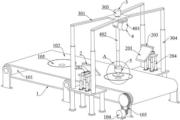
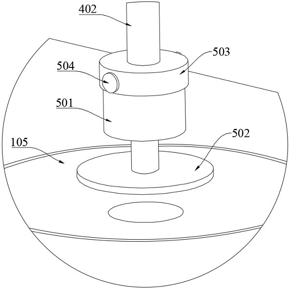
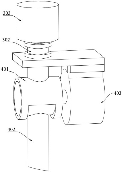
The invention discloses a polishing device for the inner wall of a satellite antenna panel. The polishing device comprises a conveying mechanism, a pair of clamping mechanisms, a rotating mechanism, an inclining mechanism and a polishing mechanism; the conveying mechanism is used for conveying the antenna panel; the pair of clamping mechanisms is arranged on the two sides of the conveying mechanism and comprises clamping blocks, the clamping blocks are connected with clamping air cylinders, and the pair of clamping air cylinders is located on the same straight line; the rotating mechanism is arranged above the conveying mechanism and comprises a support, and the support is rotationally connected with an I-shaped block; the inclining mechanism is arranged below the rotating mechanism and comprises a limiting block, the limiting block is fixed to the I-shaped block, and a telescopic rod is arranged in the limiting block in a clamped mode and can rotate in a vertical plane; and the polishing mechanism is arranged at the bottom end of the telescopic rod and comprises a polishing motor, and the polishing motor is connected with a polishing head. By adjusting the position of the polishing head, the antenna panel is polished, the polishing intensity is uniform, the polishing precision is high, the smoothness of the inner wall of the antenna panel is ensured, the polishing efficiency is high, and the polishing device is suitable for batch production.

Description

technical field [0001] The invention relates to the field of satellite antenna equipment, in particular to a polishing device for the inner wall of a satellite antenna panel. Background technique [0002] The function of the satellite dish is to collect the weak signal transmitted by the satellite and remove the noise as much as possible. Most antennas are usually parabolic, and some multi-focal antennas are a combination of spherical and parabolic. The satellite signal is concentrated to its focus after being reflected by the parabolic antenna. It has high manufacturing precision, corrosion resistance on the surface, strong wind resistance, high efficiency, high gain and durability. The satellite antenna panel is used to reflect the satellite signal energy in the starry sky and gather it into a focal point, so its surface smoothness directly affects the signal strength. [0003] The inner surface of the antenna panel needs to be polished during production. The traditional...

Claims


Application Information

Patent Timeline
IPC IPC(8): B24B29/02B24B41/00B24B41/02B24B41/06B24B47/12B24B47/22
CPCB24B29/02B24B41/005B24B41/02B24B41/06B24B47/12B24B47/22
Inventor 毛建杨波
Owner CHENGDU ANDI XINGYU ELECTRONICS SCI & TECH
Learn More