Feeding device and feeding method

A direct-up, material-storing technology, applied in the field of feeding devices, can solve the problems of inability to save labor, large floor space, and small storage capacity, and achieve the effect of saving labor, reducing floor space, and reducing losses

Inactive Publication Date: 2020-09-25
伯朗特机器人股份有限公司
View PDF10 Cites 3 Cited by
  • Summary
  • Abstract
  • Description
  • Claims
  • Application Information

AI Technical Summary

Problems solved by technology

However, the way of using the manual loading table occupies a large area, and manual loading and unloading is often required, and the storage capacity is small, which cannot save labor in a real sense.

Method used


Image

  • Feeding device and feeding method
  • Feeding device and feeding method
  • Feeding device and feeding method

Examples


Embodiment Construction

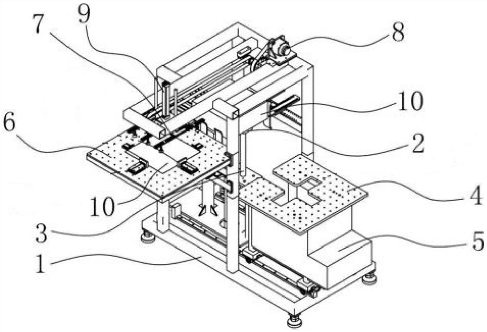
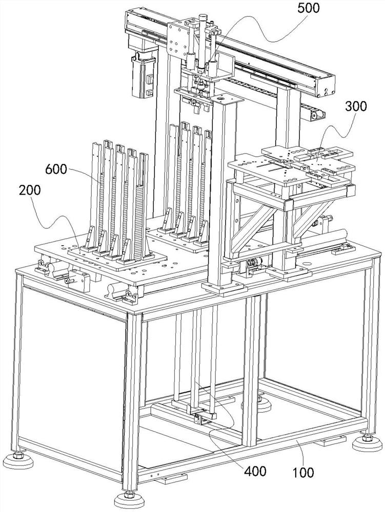
[0044] A feeding device, see figure 2 , which includes a rack 100 , a storage assembly 200 , a feeding assembly 300 , a feeding assembly 400 , and a retrieving assembly 500 . Wherein, the stocker assembly 200 is slidably installed on the top surface of the frame 100, and the stocker assembly 200 is used for placing the workpiece 600 to be loaded and having talcum powder stuck on the surface. The feeding assembly 300 is installed on the frame 100, and the feeding assembly 300 is positioned at one side of the material storage assembly 200, and one side of the storage assembly 200 is used for positioning the workpiece 600 from the storage assembly 200, to be picked up by the manipulator for post-processing. material. The feeding assembly 400 is installed on the frame 100 , the feeding assembly 400 is located directly below the storage assembly 200 , and the feeding assembly 400 lifts the workpiece 600 on the storage assembly 200 from bottom to top. The retrieving assembly 500 ...


PUM


Abstract

The invention relates to a feeding device and a feeding method. The feeding device comprises a storage assembly, a supply assembly, a feeding assembly and a taking assembly, wherein the storage assembly is used for placing workpieces; the supply assembly is located on one side of the storage assembly and used for positioning the workpieces from the storage assembly; the feeding assembly is locatedbelow the storage assembly and used for ejecting the workpieces on the storage assembly one by one from bottom to top; the taking assembly is located above the storage assembly and the feeding assembly and used for carrying the workpieces on the storage assembly to the supply assembly; the taking assembly comprises a clamping module, a first driving module and a second driving module, the clamping module abuts against side faces of the workpieces to clamp the workpieces, the first driving module is used for driving the clamping module to move back and forth between the storage assembly and the supply assembly in the horizontal direction, and the second driving module is used for driving the clamping module to ascend and descend back and forth in the vertical direction. The feeding methodadopts the feeding device for feeding.

Description

technical field [0001] The invention relates to the technical field of mechanical automatic feeding, in particular to a feeding device and a feeding method using the feeding device. Background technique [0002] Chinese Patent No. CN201510481883.7 discloses a feeding type single station feeding rack, see figure 1 , figure 1 It is a schematic diagram of the structure of a feed-type single-station loading rack, which includes: a machine base 1; a rack unit 2, which is driven by the first drive unit 3 to move back and forth along the vertical direction Movement, the first driving unit 3 is fixedly arranged on the machine base 1; the feeding unit 4 is arranged on one side of the rack unit 2, and the feeding unit 4 is driven by the second driving unit 5 to move back and forth along the horizontal direction. The second driving unit 5 is fixedly arranged on the machine base 1, and the material rack unit 2 is ejected from the feeding unit 4 from the bottom to the top and the produ...

Claims


Application Information

Patent Timeline
Patent Type & Authority Applications(China)
IPC IPC(8): B65G47/90B65G59/02
CPCB65G47/901B65G59/026
Inventor 蔡浩良
Owner 伯朗特机器人股份有限公司
Why Eureka
Try Eureka