Collecting electric field-ultrasonic wave field-centrifugal field coupled anti-scaling temperature control electric coalescence dehydrator

An ultrasonic field, coalescence dehydration technology, applied in the direction of electric/magnetic dehydration/demulsification, mechanical dehydration/demulsification, petroleum industry, etc., can solve the adverse effects of the normal operation of the electric dehydrator Large land area, high construction and operating costs, etc., to avoid hot water scaling, increase the probability of collision coalescence, and prolong the life of equipment

Active Publication Date: 2020-09-25
申文初
View PDF3 Cites 2 Cited by
  • Summary
  • Abstract
  • Description
  • Claims
  • Application Information

AI Technical Summary

Problems solved by technology

As more and more oil fields are discovered, due to different geological conditions, the quality of crude oil is not uniform, the viscosity of the produced fluid is high, and there are many impurities carried in it. Common electric dehydrators are prone to scaling on the insulating plate during the treatment process. , and the silt-like deposits formed between the electrode steel plate meshes are difficult to clean up, which will have a negative impact on the normal operation of the electric dehydrator, making the dehydration effect not ideal
In addition, ordinary electric dehydrators occupy a large area, and the construction and operation costs are relatively high.

Method used


Image

  • Collecting electric field-ultrasonic wave field-centrifugal field coupled anti-scaling temperature control electric coalescence dehydrator
  • Collecting electric field-ultrasonic wave field-centrifugal field coupled anti-scaling temperature control electric coalescence dehydrator
  • Collecting electric field-ultrasonic wave field-centrifugal field coupled anti-scaling temperature control electric coalescence dehydrator

Examples


Embodiment Construction

[0029] In order to make the object, technical solution and advantages of the present invention clearer, the present invention will be further described in detail below in conjunction with the accompanying drawings and embodiments. It should be understood that the specific embodiments described here are only used to explain the present invention, not to limit the present invention.

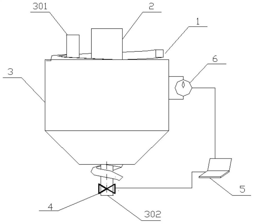
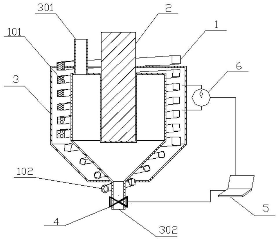
[0030] Such as figure 1 , 2 The shown electric field-ultrasonic field-centrifugal field coupled anti-scaling temperature-controlled electric coalescence dehydrator includes a thermal insulation tank 3, and the thermal insulation tank 3 has two inner and outer shells coaxially arranged, the inner shell and the outer shell The layer shell is cylindrical, and the bottom of the cylinder is conical, the bottom of the outer shell is connected with the bottom of the inner shell, and the inner shell and the outer shell are installed Filled with heat transfer oil and closed, the heat transfer oil can enha...


PUM


Abstract

The invention discloses a collecting electric field-ultrasonic wave field-centrifugal field coupled anti-scaling temperature control electric coalescence dehydrator, which comprises a heat preservation system, an ultrasonic wave generating device and a demulsification device, wherein the demulsification device comprises a spiral demulsification chamber, the spiral demulsification chamber is spirally wound on the heat preservation system, and temperature conditions are provided for demulsification through the heat preservation system; the ultrasonic generation device is arranged in the heat preservation system and used for generating an ultrasonic field; an electrode is arranged on the spiral demulsification chamber, wherein a negative electrode is arranged on the inner side of the spiral demulsification chamber, and a positive electrode is arranged on the outer side of the spiral demulsification chamber, the electrode being used for generating an electric field in the spiral demulsification chamber. The electric dehydration technology, the ultrasonic demulsification dehydration technology, the hydrocyclone separation dehydration technology and the heat treatment dehydration technology are combined, and the demulsification efficiency of the device is improved through the synergistic effect.

Description

technical field [0001] The invention belongs to an electric dehydrator, in particular to an electric coalescence dehydrator in the field of petrochemical industry. Background technique [0002] At present, most oilfields in my country use water injection to exploit oil, and because crude oil contains more impurities, most of the extracted crude oil needs to be dehydrated. Compared with methods such as gravity sedimentation, centrifugation, and chemical treatment, the electric dehydration rate is faster, the processing capacity is large, and there is no chemical pollution. The electric dehydrator has lower energy consumption, higher efficiency, safety and simplicity, and has a wider application range, and is more widely used in the dehydration treatment of crude oil. [0003] As my country's requirements for oil recovery technology continue to increase, how to efficiently separate oil from water is an urgent problem to be solved. Electrodes play a vital role in oil-water el...

Claims


Application Information

Patent Timeline
Patent Type & Authority Applications(China)
IPC IPC(8): C10G33/02C10G33/06
CPCC10G33/02C10G33/06C10G2300/208
Inventor 李彬李家琪宋英南彭海蒙
Owner 申文初
Why Eureka
Try Eureka