Wafer vertical type rotary electroplating jig and electroplating device

A technology of rotating electroplating and electroplating fixtures, applied in circuits, electrolytic processes, electrolytic components, etc., can solve the problems of large area of ​​electroplating fixtures, inaccurate control of rotation angle adjustment and electric field, etc., to improve the production area. Effectiveness of utilization, elimination of poor conductivity, and current stability

Inactive Publication Date: 2020-09-25
上海戴丰科技有限公司
View PDF6 Cites 0 Cited by
  • Summary
  • Abstract
  • Description
  • Claims
  • Application Information

AI Technical Summary

Problems solved by technology

In order to make the rotary drive mechanism above the plating solution in the electroplating pool, so as to prevent the plating solution from being corroded by the plating solution or causing large fluctuations in the agitation of the plating solution, the current rotary plating fixture is generally horizontal, that is, the wafer is in a horizontal state during electroplating, but the horizontal Type electroplating fixture occupies a large area, which affects production efficiency
In the Chinese Taiwan patent document with the certificate number TWI410531B, a vertical electroplating equipment and its electroplating method are recorded. The vertical type can save floor space, but its driving method adopts electromagnetic actuation, which has two major disadvantages : First, the adjustment and control of the speed and rotation angle are not accurate, which is not conducive to debugging to the optimal speed; second, the electromagnetic will have a certain impact on the electric field of electroplating, which will have a negative effect on the uniformity of wafer coating thickness

Method used


Image

  • Wafer vertical type rotary electroplating jig and electroplating device
  • Wafer vertical type rotary electroplating jig and electroplating device
  • Wafer vertical type rotary electroplating jig and electroplating device

Examples


Embodiment Construction

[0026] The following will clearly and completely describe the technical solutions in the embodiments of the present invention with reference to the accompanying drawings in the embodiments of the present invention. Obviously, the described embodiments are only some, not all, embodiments of the present invention. Based on the embodiments of the present invention, all other embodiments obtained by persons of ordinary skill in the art without creative efforts fall within the protection scope of the present invention.

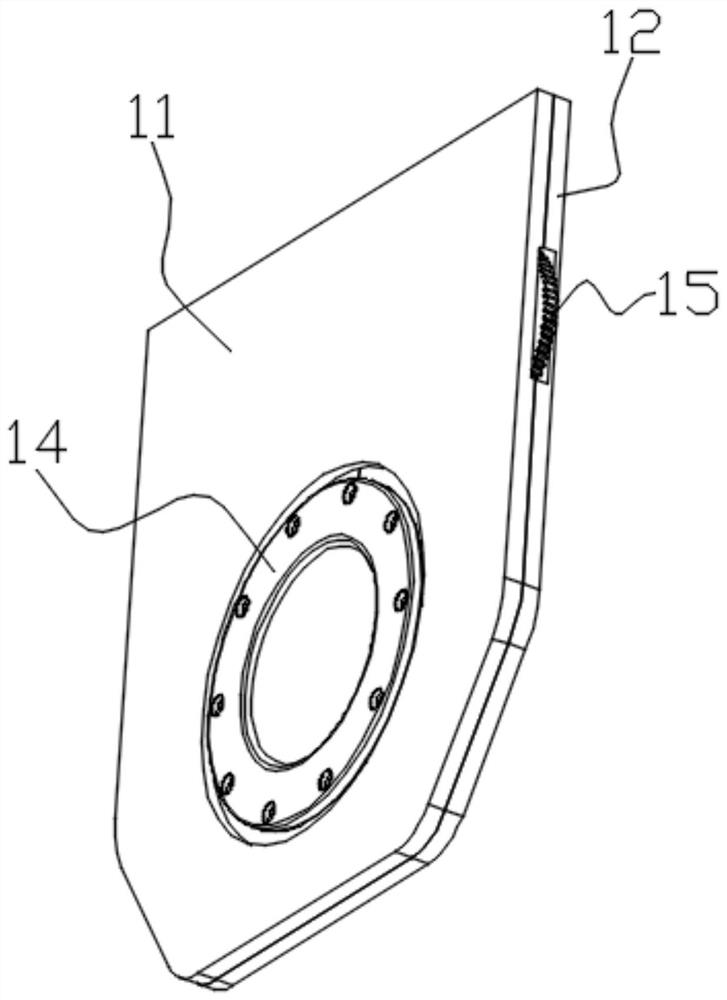
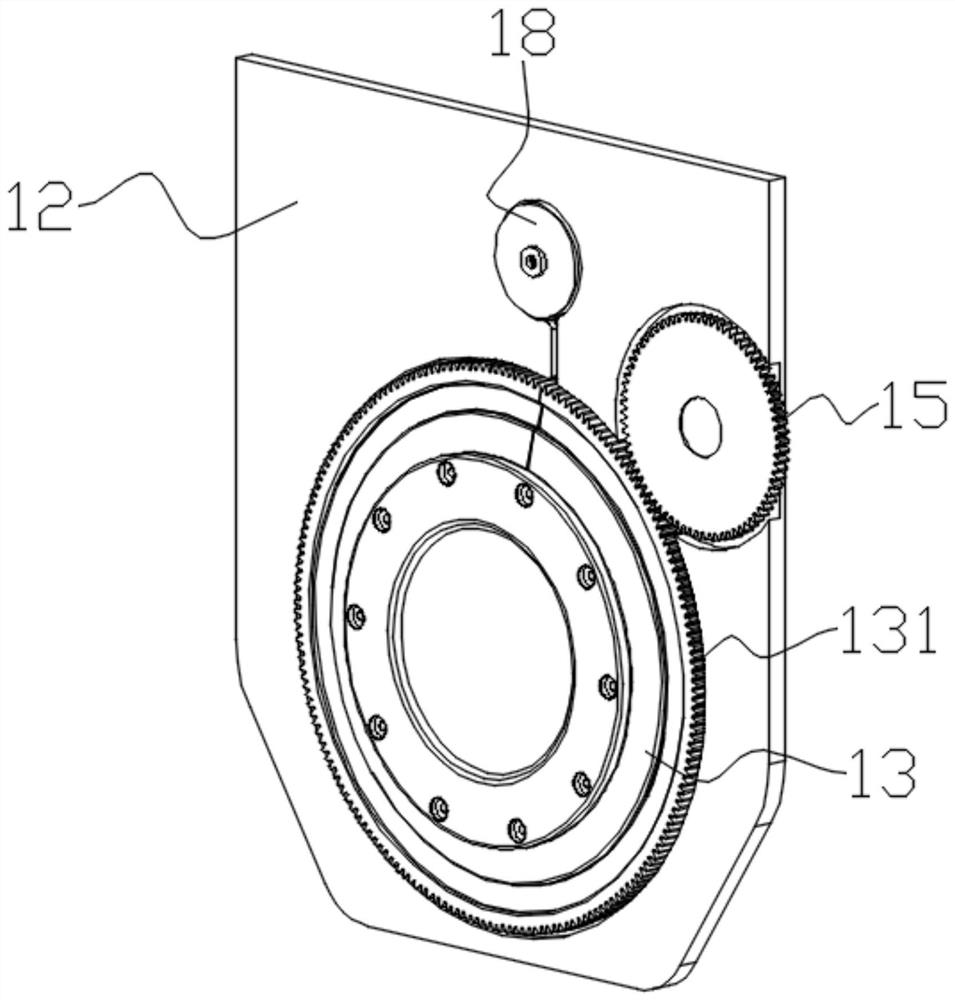
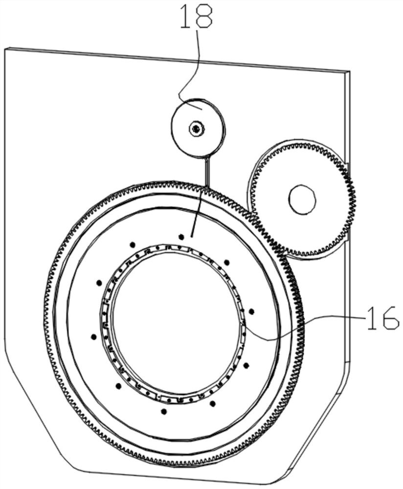
[0027] Such as Figure 1-3 As shown in . The transmission mechanism for the rotation of the swivel 13, the first plate body 11 or the second plate body 12 is provided with a power connector 21 for connecting with the power supply cathode, the swivel ring 13 is provided with an annular cathode electrode piece 16, and the annular cathode electrode piece 16 It is electrically connected to the power connector 21 through wires, and also includes a wire reel 18, and the...


PUM


Abstract

The invention provides a wafer vertical type rotary electroplating jig and an electroplating device. The electroplating jig comprises a first plate body which is vertically arranged, a second plate body, a rotating ring, a press plate and a drive mechanism for driving the rotating ring to rotate, wherein an annular cathode electrode slice is arranged on the rotating ring and electrically connectedwith a power connector through a wire, the wire winds around a wire coil, and the electroplating jig further comprises a reset mechanism for promoting the wire coil to take up and revolve; and the drive mechanism comprises a first drive tooth profile part arranged on the rotating ring and a first drive gear. The electroplating jig is vertically arranged, can effectively reduce the floor area andincreases the utilization rate of a production site. By means of a gear drive mode, the drive gear is conveniently arranged between the first plate body and the second plate body without agitating electroplate liquid, the drive accuracy is high, and rotating speed and switching of forward and reverse rotation of the rotating ring are convenient and accurate to operate and control, so that the bestwafer plating thickness consistency is obtained by adjustment.

Description

technical field [0001] The invention relates to the technical field of wafer packaging wet process, in particular to a wafer vertical rotary electroplating jig and an electroplating device. Background technique [0002] During the wet process of wafer packaging, due to the slight difference in the electric field strength at each position of the wafer, there is a certain uniformity difference in the thickness of the coating. In order to improve the uniformity of the thickness of the wafer electroplating coating, a rotary electroplating fixture has appeared, that is, the wafer is continuously rotated during the electroplating process. This method can effectively improve the uniformity of the coating. In order to make the rotary drive mechanism above the plating solution in the electroplating pool, so as to prevent the plating solution from being corroded by the plating solution or causing large fluctuations in the agitation of the plating solution, the current rotary plating f...

Claims


Application Information

Patent Timeline
Patent Type & Authority Applications(China)
IPC IPC(8): C25D17/06C25D21/10C25D7/12
CPCC25D7/12C25D17/001C25D17/06C25D21/10
Inventor 何志刚
Owner 上海戴丰科技有限公司
Why Eureka
Try Eureka