

Impact test mechanism of steering oil pump
A technology of impact test and steering oil pump, which is applied in pump test, parts of pumping device for elastic fluid, pump, etc. It can solve the problems that the test is easily terminated, affects the continuation of the test, and cannot meet the actual use, etc., to achieve Improve the success rate of the experiment and avoid the effect of controlling the rotation of the spindle
- Summary
- Abstract
- Description
- Claims
- Application Information
AI Technical Summary
Problems solved by technology
Method used
Image

Examples
Embodiment 1
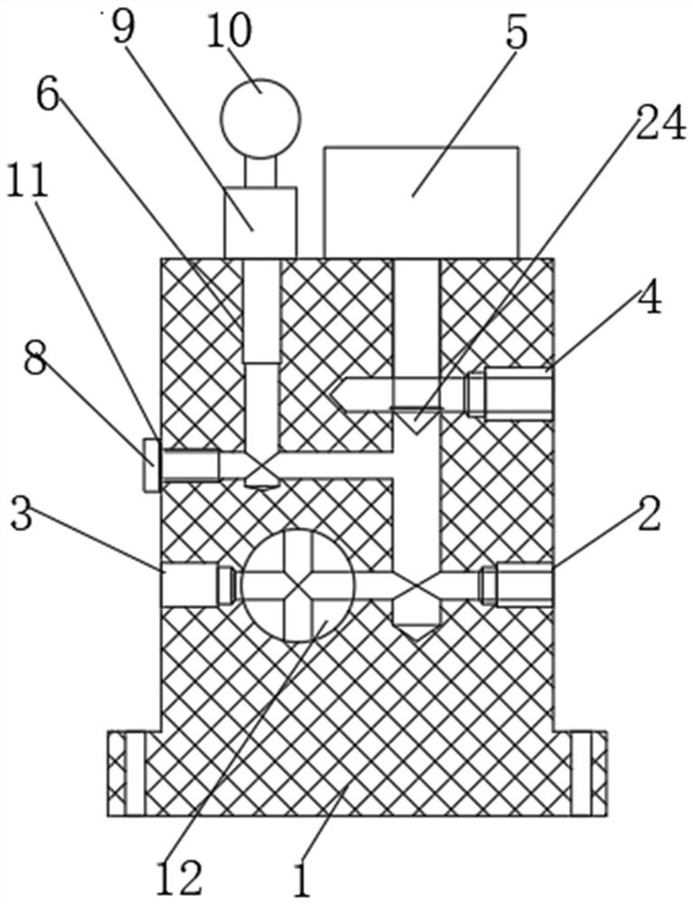
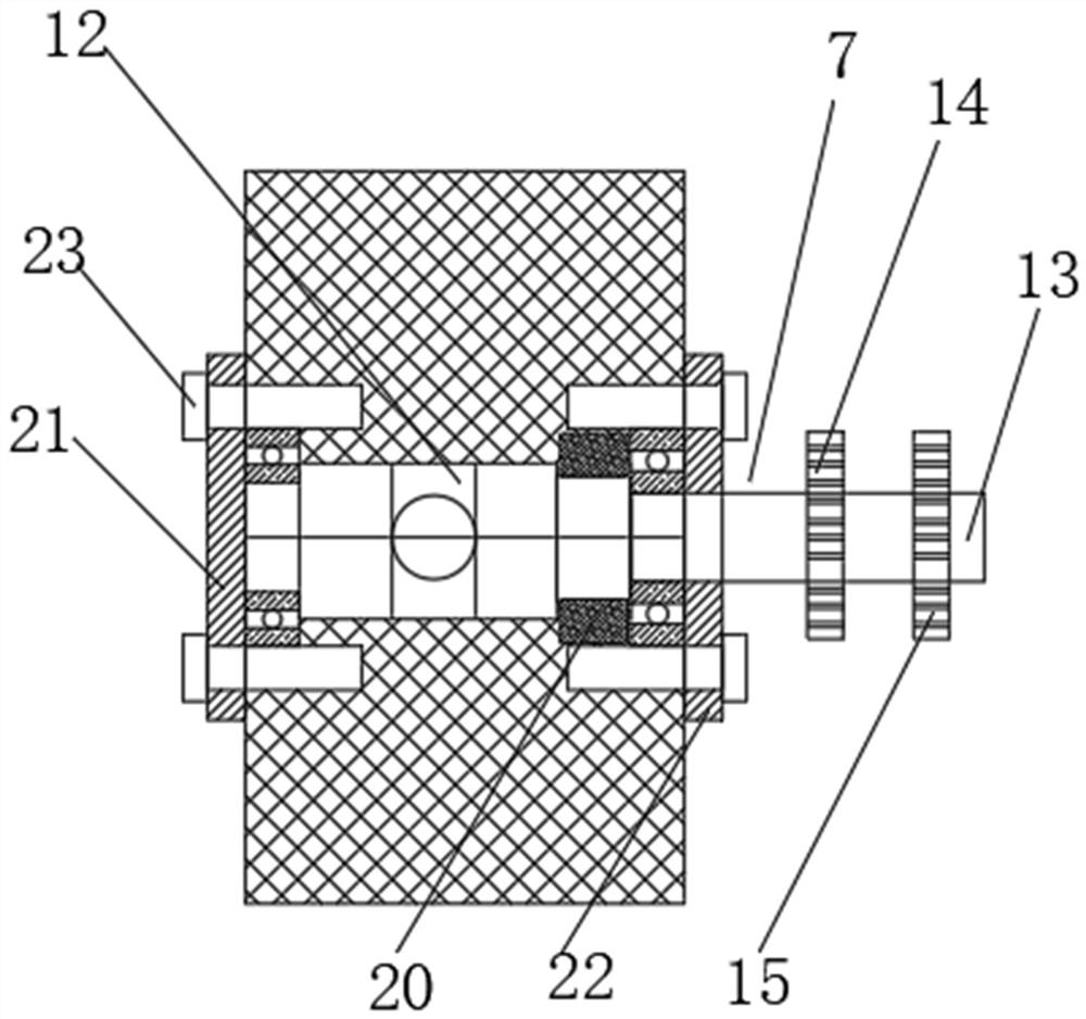
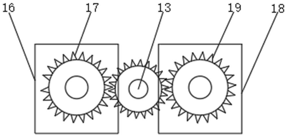
[0027] Such as Figure 1-4 As shown in the figure, an impact test mechanism for a steering oil pump includes a fixed base (1), on which a pressure regulating mechanism (5), a pressure measuring mechanism (6) and a loading mechanism (7) are respectively arranged, and the fixed base The interior of (1) is respectively provided with an oil inlet passage, an oil outlet passage and an oil return passage, the oil inlet (2) of the oil inlet passage, the oil outlet (3) of the oil outlet passage and the oil return port of the oil return passage ( 4) Set on the fixed base (1) respectively, the oil return passage is set between the oil inlet passage and the oil outlet passage, the oil inlet passage, the oil outlet passage and the oil return passage are all connected and connected, and the pressure regulating mechanism (5) is set The magnitude of the loading pressure can be changed, the set pressure measuring mechanism (6) can measure the impact pressure value, and the set loading mechani...
Embodiment 2
[0035] Such as Figure 1-4 As shown in the figure, an impact test mechanism for a steering oil pump includes a fixed base (1), on which a pressure regulating mechanism (5), a pressure measuring mechanism (6) and a loading mechanism (7) are respectively arranged, and the fixed base The interior of (1) is respectively provided with an oil inlet passage, an oil outlet passage and an oil return passage, the oil inlet (2) of the oil inlet passage, the oil outlet (3) of the oil outlet passage and the oil return port of the oil return passage ( 4) Set on the fixed base (1) respectively, the oil return passage is set between the oil inlet passage and the oil outlet passage, the oil inlet passage, the oil outlet passage and the oil return passage are all connected and connected, and the pressure regulating mechanism (5) is set The magnitude of the loading pressure can be changed, the set pressure measuring mechanism (6) can measure the impact pressure value, and the set loading mechani...
PUM
 Abstract
Description
Claims
Application Information