FRP rib and concrete bonding performance load holding and testing device and using method thereof

A bonding performance and testing device technology, which is applied in the direction of measuring devices, mechanical devices, instruments, etc., can solve the problems that it is difficult to ensure the axial tension of the reinforcement, and achieve the effect of simple structure, small space, and not easy to rust

Active Publication Date: 2020-09-25
YANGZHOU UNIV
View PDF9 Cites 2 Cited by
  • Summary
  • Abstract
  • Description
  • Claims
  • Application Information

AI Technical Summary

Problems solved by technology

[0006] Aiming at the problem that the FRP tendon and concrete bond performance sustaining test device is difficult to ensure the axial tension of the tendon due to the manual rotation of the nut, the invention provides a FRP tendon and concrete bond performance sustain load and test device and its use method

Method used


Image

  • FRP rib and concrete bonding performance load holding and testing device and using method thereof
  • FRP rib and concrete bonding performance load holding and testing device and using method thereof
  • FRP rib and concrete bonding performance load holding and testing device and using method thereof

Examples


Embodiment 1

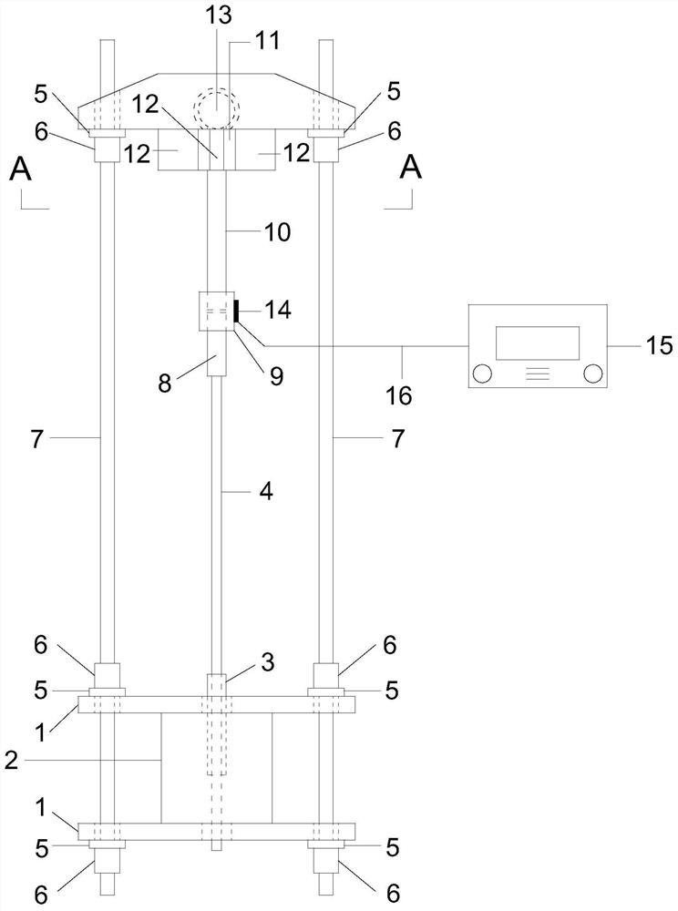
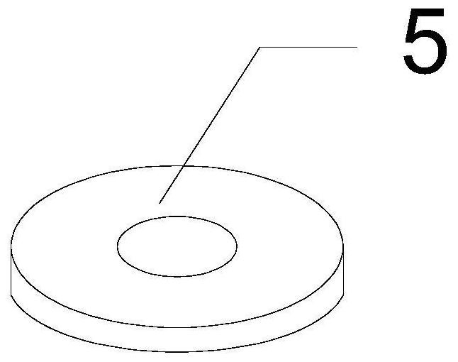
[0035] The present invention is used as FRP bar and concrete bonding performance load-bearing test device, as figure 1As shown, it includes square steel plate 1, concrete cube test block 2, PVC pipe 3, FRP bar 4, steel washer 5, finish-rolled nut 6, prestressed finish-rolled threaded steel bar 7, bonding sleeve 8, connecting sleeve 9, Connecting rod 10, reinforced round steel pipe 11, rectangular stiffened steel plate 12, spherical hinge 13, strain gauge 14, resistance strain gauge 15, connecting wire 16. The end of the ball hinge is a variable-section steel plate with circular reserved holes at the four corners, and a groove is reserved in the middle of the variable-section steel plate for rotational contact with the ball hinge. In order to avoid becoming bulky due to the large thickness of the steel plate, the steel plate on the top is designed as a variable-section steel plate.

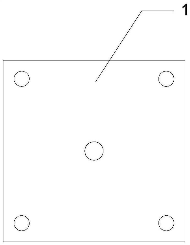
[0036] Such as figure 2 As shown, there are five reserved holes on the square steel plate 1,...

Embodiment 2

[0045] The present invention is used as FRP tendon and concrete bonding property testing device, as Figure 6 As shown, on the basis of the load-bearing device, a newly added through-type drawing instrument 17, a displacement gauge 18, and two square steel plates in the middle, one of which is placed between the connecting sleeve 9 and the rectangular stiffener steel plate 12 The center-through drawing instrument 17 above the support is fixed below it with steel washers 5 and finish-rolled nuts 6, and another steel plate is arranged above the center-through drawing instrument 17 to withstand the rectangular stiffener steel plate 12; Described rectangular stiffener steel plate 12, is arranged in the square steel plate 1 below rectangle conveniently withstands; Described piercing type drawing instrument 17 is used for applying drawing force; Described displacement meter 18 is respectively arranged on piercing type drawing instrument 17 above the square steel plate 1 and the lowe...


PUM


Abstract

The invention discloses an FRP rib and concrete bonding performance load holding and testing device and a using method thereof. By adopting a method of adding a spherical hinge at one end, an end steel plate is pushed in parallel to ensure that the axis of a rib material is pulled. The device does not need to adopt an independent load sensor, and adopts a method of adhering a resistance strain gauge to a connecting sleeve with internal threads and an outer smooth circle, so the device also serves as the load sensor, the test device is simplified, and the cost problem that a large number of load sensors need to be occupied for long-term load holding is reduced. The device is simple to operate and can effectively keep a drawing force. According to the invention, a load holding test and an adhesive property test are combined into a whole, and the test device is formed on the basis of the load holding device without using two devices to carry out load holding test and test on the adhesiveproperty of the FRP rib and the concrete interface under the long-term action of the load.

Description

technical field [0001] The invention belongs to the field of civil engineering, and in particular relates to a load-holding and testing device for the bonding performance of FRP bars and concrete and a method for using the same. Background technique [0002] As a building material with excellent performance, steel bar is widely used in modern engineering structures. However, in recent years, the problems of corrosion and deterioration of reinforced concrete structures and steel structures have become increasingly serious, among which corrosion of steel bars is the most common. Corrosion of steel bars has a serious impact on the bearing capacity and applicability of the structure, not only affecting the normal use and life of the structure, but also causing a large number of safety and accident hazards, and the resulting maintenance and reinforcement costs are also quite expensive of. Aiming at the problem of corrosion of concrete structures, the current anti-corrosion meas...

Claims


Application Information

Patent Timeline
Patent Type & Authority Applications(China)
IPC IPC(8): G01N19/04
CPCG01N19/04
Inventor 葛文杰王冠严卫华王仪高培琦仇胜伟曹大富陆伟刚
Owner YANGZHOU UNIV
Why Eureka
Try Eureka