Efficient heat dissipation device for electronic components

A technology for electronic components and cooling devices, which is applied in the field of high-efficiency cooling devices for electronic components, can solve the problems of increased circuit board thickness, affecting installation, and insufficient heat dissipation, so as to reduce thickness, reduce installation difficulty, and increase flexibility. Effect

Inactive Publication Date: 2020-09-25
郑州威科特电子科技有限公司
View PDF7 Cites 6 Cited by
  • Summary
  • Abstract
  • Description
  • Claims
  • Application Information

AI Technical Summary

Problems solved by technology

[0005] The purpose of the present invention is to solve the shortcomings in the prior art that there is insufficient heat dissipation for high-heating electronic components, and the heat dissipation device increases the thickness of the entire circuit board, which affects the installation. A high-efficiency heat dissipation device for electronic components is proposed

Method used


Image

  • Efficient heat dissipation device for electronic components
  • Efficient heat dissipation device for electronic components
  • Efficient heat dissipation device for electronic components

Examples


Embodiment 1

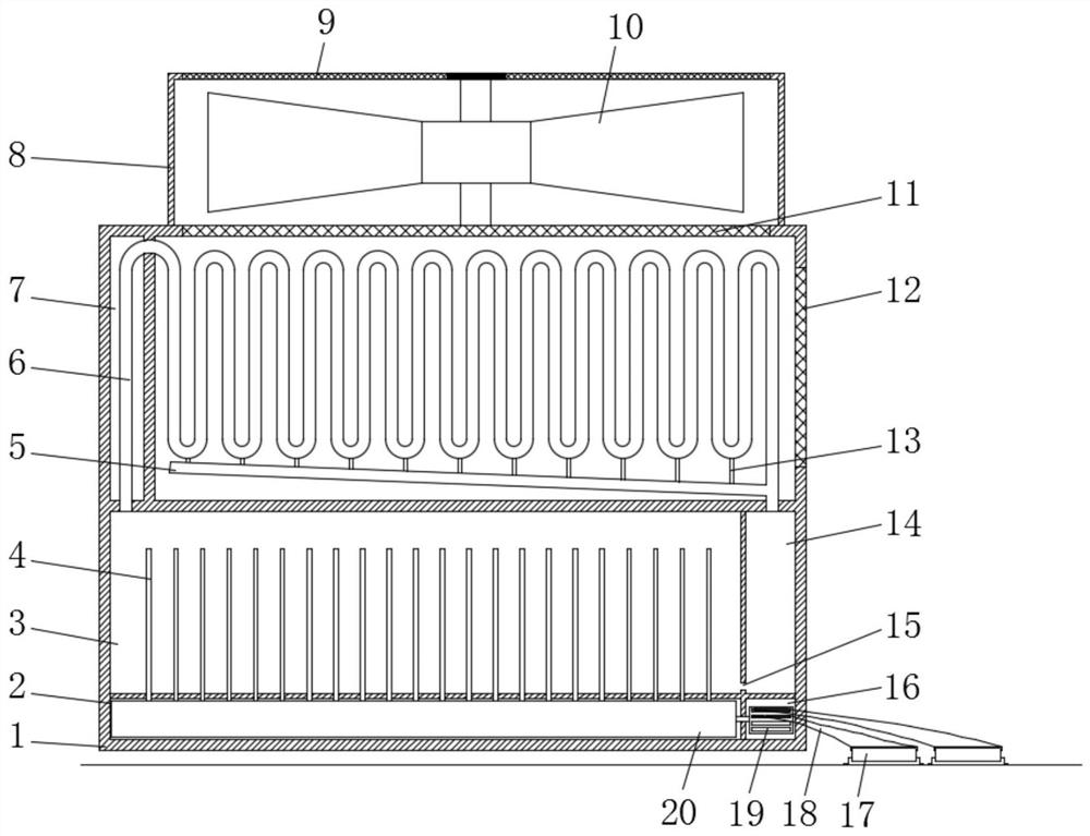
[0028] refer to Figure 1-4 , a high-efficiency heat dissipation device for electronic components, including a heat dissipation box 1 and an electronic component 17, a fan box 8 is installed on the upper end of the heat dissipation box 1, a fan 10 is installed in the fan box 8, and an upper top wall of the fan box 8 is embedded A third dust-proof net 9 is installed, and the cooling box 1 is divided into a condensation chamber 7, a heat absorption chamber 3, a return chamber 14, a heating chamber 2, and a heat conduction module chamber 16 from top to bottom. mechanism;

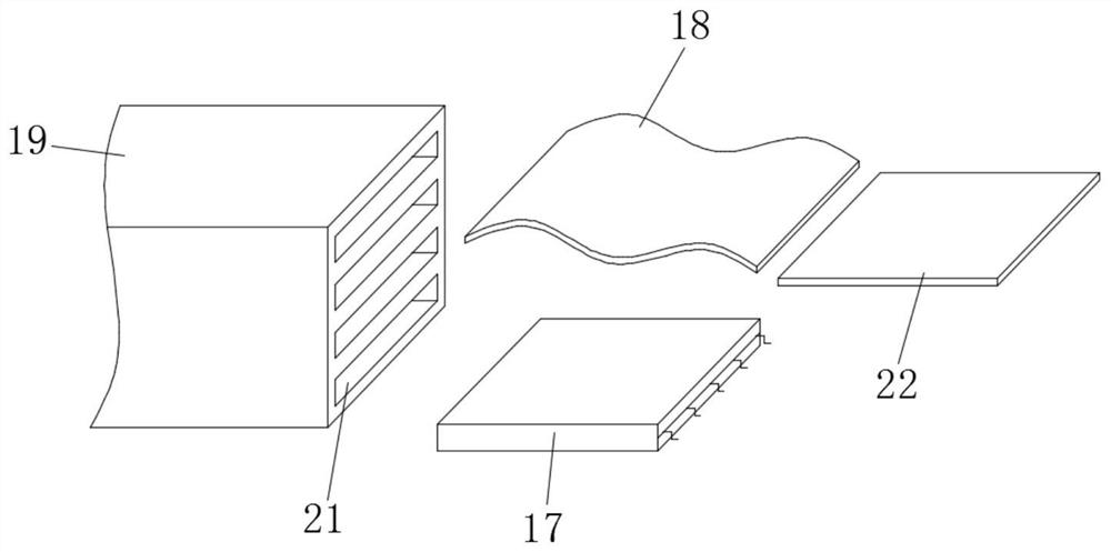
[0029] A heat conduction module block 19 is installed in the heat conduction module cavity 16, and a flexible graphite connecting sheet 18 is inserted on the heat conduction module block 19, and a plurality of slots 21 are symmetrically opened at both ends of the heat conduction module block 19, and the flexible graphite connection One end of the piece 18 is inserted in the slot 21 for transferring heat to the...

Embodiment 2

[0034] refer to Figure 5 , a high-efficiency heat dissipation device for electronic components provided in this embodiment is basically the same as Embodiment 1, the difference is that:

[0035] The upper bottom wall of the condensation chamber 7 is embedded with a first dust-proof net 11, and the side wall of the condensation chamber 7 is embedded with a second dust-proof net 12, and the first dust-proof net 11 communicates with the condensation chamber 7 and the outside air. , and the second dust-proof net 12 communicates with the fan box 8 and the condensation chamber 7, that is, the fan box 8 is installed on the outer wall of the condensation chamber 7, and the fan box 8 is installed on the side of the cooling box 1 to reduce the thickness of the cooling device and reduce the circuit. Board installation difficulty.

[0036] In this embodiment, according to the arrangement of the electronic components 17 that need to be dissipated on the circuit board, select a suitable f...


PUM


Abstract

The invention discloses an efficient heat dissipation device for an electronic component. The efficient heat dissipation device comprises a heat dissipation box and electronic components, wherein a fan box is installed at the upper end of the heat dissipation box, a fan is installed in the fan box, a third dustproof net is embedded in the upper top wall of the fan box, the heat dissipation box issequentially divided into a condensation cavity, a heat absorption cavity, a reflux cavity, a heating cavity and a heat conduction module cavity from top to bottom, and a condensation and heat dissipation mechanism is installed in the condensation cavity. According to the invention, the device is reasonable in structural design; a condensation and reflux structure is formed by a condensation and heat dissipation pipe, a fan, a heat absorption cavity and a reflux cavity, so that heat dissipation can be circulated; the fan can be fixed on the side surface, so that the thickness of the heat dissipation device is reduced, and the installation difficulty is reduced; a graphite heat conduction sheet and a flexible graphite connecting sheet can be connected and attached to the surface of any electronic component, so that the applicability and pertinence of the device are improved; and a heat conduction module block can select the proper flexible graphite connecting sheets according to the number of electronic components needing heat dissipation, so that energy losses are reduced.

Description

technical field [0001] The invention relates to the field of heat dissipation of electronic components, in particular to an efficient heat dissipation device for electronic components. Background technique [0002] Electronic components are components of electronic components and small electrical machines and instruments. They are often composed of several parts and can be used in similar products; they often refer to certain parts in industries such as electrical appliances, radios, and instruments, such as capacitors and transistors. The general term for sub-components such as springs, hairsprings, and springs. Usually on the circuit board, you can see a variety of electronic components welded on the board. Electronic components need to be powered during use, and electronic components have Internal resistance, with internal resistance, heat will be generated after power-on. Some electronic components have small internal resistance, and the heat generated after power-on is ...

Claims


Application Information

Patent Timeline
Patent Type & Authority Applications(China)
IPC IPC(8): H05K7/20
CPCH05K7/2029H05K7/20318H05K7/20136H05K7/2039
Inventor 张晓静宋芹
Owner 郑州威科特电子科技有限公司
Why Eureka
Try Eureka