Fluid container having device for fill level monitoring

A fluid container, filling level technology, applied in the direction of buoy level indicator, liquid/fluid solid measurement, measuring device, etc., can solve the leakage signal, undetected, unreliable detection of position encoder clogging or Blockage and other problems, to achieve the effect of large filling height, simple design, and reduced size

Pending Publication Date: 2020-09-25
CONTINENTAL AUTOMOTIVE TECH GMBH
View PDF11 Cites 0 Cited by
  • Summary
  • Abstract
  • Description
  • Claims
  • Application Information

AI Technical Summary

Problems solved by technology

In this respect, for example, a clogged or jammed position encoder cannot be reliably detected
It is also the case in known devices that only extreme leaks can be signaled, for example in the event of a complete failure of the brake circuit
On the other hand, a gradual leak may remain undetected for a longer period of time

Method used


Image

  • Fluid container having device for fill level monitoring
  • Fluid container having device for fill level monitoring
  • Fluid container having device for fill level monitoring

Examples


Embodiment Construction
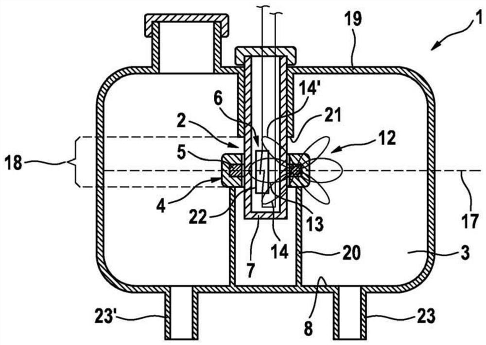
[0025] figure 1

[0026] The known fluid container 1 has a housing 19 which can be filled with a fluid. The hydraulic ports 23, 23' connect the interior space 3 of the container 19 to a braking system (not shown here) and enable circulation of fluid. In order for the brake system to function reliably, a minimum amount of fluid is required which defines a minimum fill level in a manner dependent on the state of the container 19 and possibly on a defined safety factor in the housing 19 .

[0027] The conduit 7 is arranged vertically aligned in the inner space 3 of the housing 19 . The signaling unit 6 with the reed switch 22 is accommodated in the conduit 7 . Through its position, the reed switch 22 defines a switching point 17 which is arranged at the height of the minimum fill level to be monitored by the structural design.

[0028] Position encoder 4 is guided on conduit 7 . The position encoder 4 is designed as an annular float which floats on the surface of the fluid s...


PUM


Abstract

The invention relates to a fluid container (1) having a device (2) for fill level monitoring of a fluid, the device (2) being arranged in an interior chamber (3) within the fluid container (1) and comprising a position encoder (4), which can be moved in a linear manner and has a magnet element (5), the position of which correlates to the fill level of the fluid in the fluid container (1), and a signal unit (6) which generates at least one electrical signal as a function of the position of the magnet element (5). In order to provide an improved fluid container (1), which can be constructed to be lighter and more compact, together with an expanded scope of functionality of the measurement device (2), according to the invention, the signal unit (6) has at least one Hall element (11) for detecting the position of the magnet element (5).

Description

technical field [0001] In various embodiments, fluid containers having means for monitoring the fill level of introduced fluid are known and widely available. Background technique [0002] DE 10 2010 042 646 A1 discloses, for example, a fluid container which is designed as a brake fluid container for a brake system of a motor vehicle. The fluid container has means for detecting a minimum fill level of the introduced brake fluid. For this purpose, the device has a signaling unit with an inexpensive and operationally reliable reed switch, which is activated by a ring magnet and closes the circuit in the process. The reed switch is arranged in the container at the minimum admissible fill level in a vertical cylindrical conduit. The ring magnet is accommodated in the ring float and together with the ring float forms a position encoder which is arranged around the conduit and guided on it. A reed switch only responds digitally to magnetic field strengths above a certain thresh...

Claims


Application Information

Patent Timeline
Patent Type & Authority Applications(China)
IPC IPC(8): G01F23/74G01F23/00
CPCG01F23/74G01F23/0007G01F23/72
Inventor S·施利希特H·克莱默M·拉弗W·克雷布斯S·奥特曼
Owner CONTINENTAL AUTOMOTIVE TECH GMBH
Why Eureka
Try Eureka