Novel dual-blade-groove cutting tool

A new type of cutting edge technology, applied in the field of mechanical parts processing, can solve the problems of inability to complete normal processing, large tool width contact surface, large processing vibration, etc., to solve the problems of tool chatter, improved tool durability and low processing efficiency. Effect

Pending Publication Date: 2020-09-29
INST OF MACHINERY MFG TECH CHINA ACAD OF ENG PHYSICS
View PDF0 Cites 2 Cited by
  • Summary
  • Abstract
  • Description
  • Claims
  • Application Information

AI Technical Summary

Problems solved by technology

[0003] The technical problem to be solved by the present invention is: when the conventional standard groove cutter is processing the annular groove of weakly rigid parts, due to the poor rigidity of the workpiece, the contact surface of the blade width is large, and the cutting force is radial, resulting in large processing vibration and unable to complete normal processing , the present invention provides a novel double-edged flute cutter that solves the above problems

Method used


Image

  • Novel dual-blade-groove cutting tool
  • Novel dual-blade-groove cutting tool
  • Novel dual-blade-groove cutting tool

Examples


Embodiment 1

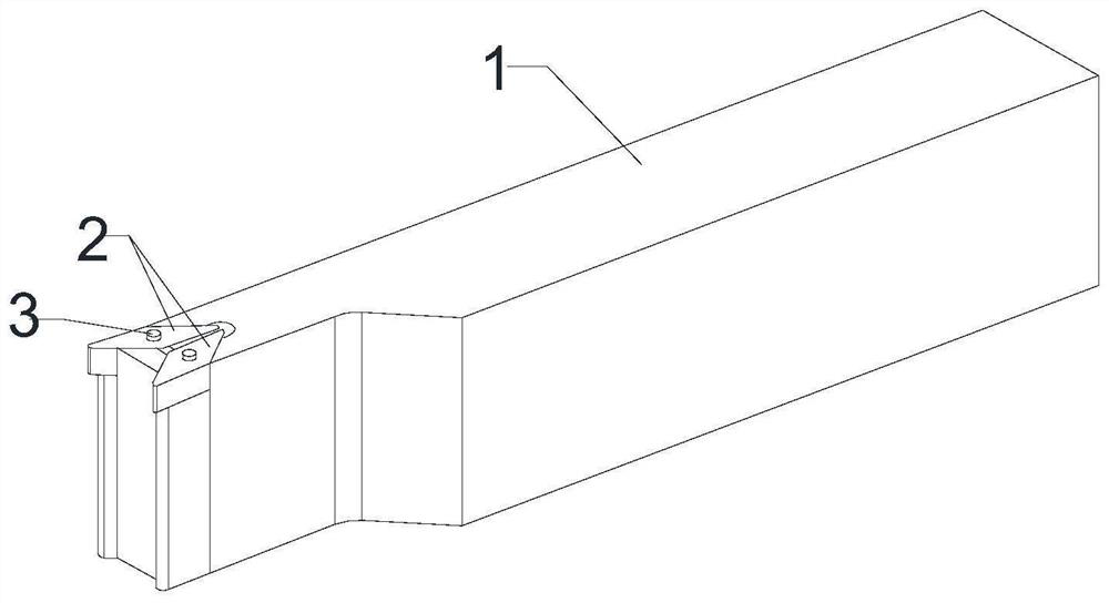
[0038] This embodiment provides a novel double-edged groove cutter, comprising a knife bar 1 and two profiled blades 2 with identical structures and sizes, and the two profiled blades 2 are installed on the same working plane at the end of the knife bar 1; One of the profiling blades 2 has an angle α to the left of the main knife edge at the working end, and the other profiling blade 2 has an angle α to the right of the main knife edge at the working end, and the two profiling blades 2 are symmetrically distributed in left and right mirror images, where α is an acute angle , the main cutting edges of the working ends of the two profiling blades 2 are located on a straight line in the plane. The groove cutter is used to machine the inner ring groove of the long axis parts.

Embodiment 2

[0040] Further improvement on the basis of Example 1, the angle α is equal to 35°, that is, one profiling blade 2 deviates to the left by 35°, and the other profiling blade 2 deviates to the right by 35°; both profiling blades 2 pass through the screw 3 It is fixed on the same working surface at the end of the tool bar 1. Specifically, a through hole is provided at the geometric center of the two profiling blades 2. After the screw 3 passes through the through hole, it is threaded and fixed on the same working surface at the end of the tool bar 1. work surface.

Embodiment 3

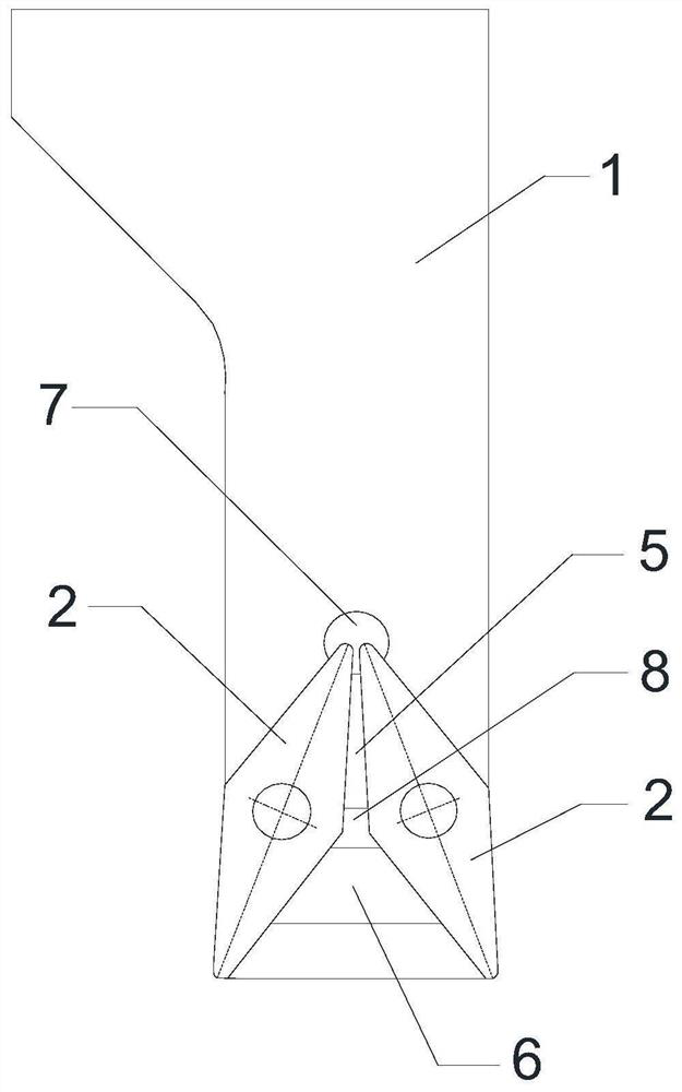
[0042]As a further improvement on the basis of Embodiment 2, a mounting groove 4 is opened on a working surface at the end of the cutter bar 1, and two profiling blades 2 are inserted into the mounting grooves to be fixed. The adjacent two side walls away from the free end of the tool bar 1 on the mounting groove 4 are V-shaped structures, and the inner bottom surface of the mounting groove 4 is protruded with a wedge-shaped limiter I5 and a wedge-shaped limiter II6, and the wedge-shaped limiter I5 and the wedge-shaped limiter The position piece II6 is located on the center line of the mirror image of the two profiling blades 2; the two side walls of the non-working end of the main knife edge of one of the profiling blades 2 are respectively connected to the side wall of the V-shaped structure and one side of the wedge-shaped stopper I5 The inclined walls are in contact with each other, and the side wall of the main knife edge of the working end of the profiling blade 2 protrud...


PUM


Abstract

The invention discloses a novel dual-blade-groove cutting tool. The cutting tool comprises a tool bar and two profiling cutting blades; the two profiling cutting blades are installed on a same workingsurface of the end part of the tool bar; a main blade bit of a working end of one of the profiling cutting blades is skew to the left by an angle alpha, and a main blade bit of a working end of the other profiling cutting blade is skew to the right by an angle alpha; and the two profiling cutting blades are symmetrically distributed, and alpha is an acute angle. Compared with a standard groove cutting tool, the contacting area between the cutting tool and a cutting workpiece is reduced in the feeding process along the radial direction, so the radial cutting force is reduced; groove processingis conducted by back-and-forth and layer-by-layer feeding of the cutting tool along the axial direction, so the cutting force generated by processing is mainly axial and the radial cutting force is greatly reduced; and the problem of vibration in the process of processing is solved, the processing precision is improved, and processing efficiency is conveniently improved.

Description

technical field [0001] The invention relates to the technical field of mechanical parts processing, in particular to a novel double-edged groove cutter. Background technique [0002] In the machining of complex profiles, tool removal is required due to a large amount of blank allowance, and parameters such as tool accuracy and structural form will directly affect product quality and processing costs. Especially for the processing of large weakly rigid parts, since it is necessary to process an inner annular groove with a depth greater than 30mm and an aspect ratio greater than 1 at the mouth of the part, the groove is more than 1m away from the clamping part, so it is easy to vibrate during processing. Moreover, the single batch of this part is large and the precision requirements are high, so the development of high-efficiency cutting tools is particularly important while seeking high-precision turning processing. For the processing of this part, a standard groove cutter (...

Claims


Application Information

Patent Timeline
Patent Type & Authority Applications(China)
IPC IPC(8): B23B27/06B23B27/14
CPCB23B27/06B23B27/14
Inventor 李球飞黄勇魏俊立黄新宇黄志平
Owner INST OF MACHINERY MFG TECH CHINA ACAD OF ENG PHYSICS
Why Eureka
Try Eureka