Low-noise high-speed centrifugal grinding and polishing machine

A high-speed centrifugal and low-noise technology, applied in the field of polishing machines, can solve the problems of inability to polish various parts, low work efficiency, large drum volume, etc., and achieve the effects of weight reduction, high work efficiency and stable operation

Pending Publication Date: 2020-09-29
方国权
View PDF0 Cites 2 Cited by
  • Summary
  • Abstract
  • Description
  • Claims
  • Application Information

AI Technical Summary

Problems solved by technology

The problems existing in this kind of polishing machine are: 1. Since the drum is large and heavy, and there is only one discharge port, it is very inconvenient to operate each time when discharging and retrieving the material. When loading and unloading the drum, two people need to lift it together 1. Low work efficiency; 2. There is only one horizontal rotary drum, and various parts can only be mixed in one drum for polishing, and various parts cannot be sorted for polishing; 3. The noise is loud during operation

Method used


Image

  • Low-noise high-speed centrifugal grinding and polishing machine
  • Low-noise high-speed centrifugal grinding and polishing machine
  • Low-noise high-speed centrifugal grinding and polishing machine

Examples


Embodiment Construction

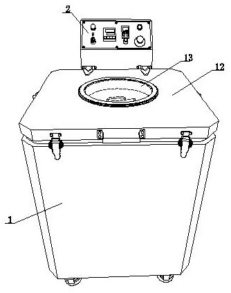
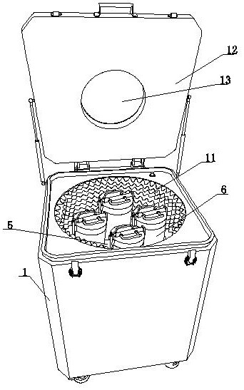
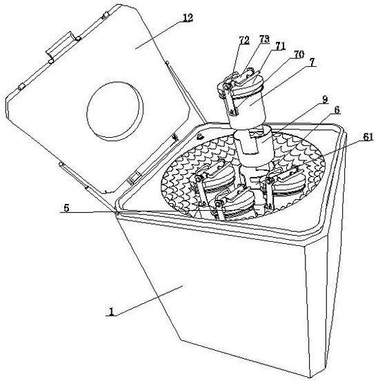
[0025] Such as Figure 1-Figure 4 As shown, the low-noise high-speed centrifugal grinding and polishing machine of the present invention includes an outer shell 1, an industrial control system 2, a driving device 3 electrically connected to the industrial control system 2, and a centrifugal polishing device. The inner cavity of the outer casing 1 and the vertical main shaft 4 that is transmission-connected with the drive device 3, the main turntable 5 installed on the top of the main turntable 4, and at least two vertical centrifugal cylinder seats 6 installed on the main turntable 5 , the centrifugal grinding cylinder 7 of the device that can be loaded and removed in the centrifugal cylinder seat 6, each of the centrifugal cylinder seats 6 is connected to the main rotating disk 5 through the centrifugal rotating shaft 8 passing through the main rotating disk 5, and the centrifugal rotating shaft 8 The lower end is connected with the main rotating shaft 4 through the transmiss...


PUM


Abstract

The invention discloses a low-noise high-speed centrifugal grinding and polishing machine. The centrifugal grinding and polishing machine comprises an outer shell, an industrial control system, a driving device and a centrifugal polishing device, and is characterized in that the centrifugal polishing device comprises a vertical main rotating shaft arranged in an inner cavity of the outer shell andin transmission connection with the driving device, a main rotating disc arranged at the top of the main rotating shaft, at least two vertical centrifugal barrel bases arranged on the main rotating disc, and centrifugal grinding barrels capable of being arranged in the centrifugal barrel bases in a loading and unloading mode; and the centrifugal barrel bases are rotationally connected to the mainrotary disc through centrifugal rotary shafts penetrating through the main rotary disc, the lower ends of the centrifugal rotary shafts are connected with the main rotary shaft through transmission assemblies, and the centrifugal barrel bases and the centrifugal grinding barrels are driven to centrifugally rotate at a high speed through the transmission assemblies and the centrifugal rotary shafts while the main rotary shafts drive the main rotary disc to rotate. According to the low-noise high-speed centrifugal grinding and polishing machine, during polishing operation, material taking and discharging operation is simple and easy, various parts can be classified in different centrifugal grinding cylinders to be ground and polished at the same time, the working efficiency is high, and noise is low during operation.

Description

technical field [0001] The invention relates to the field of polishing machines, in particular to a low-noise, high-speed centrifugal grinding and polishing machine. Background technique [0002] The grinding and polishing machine is mainly suitable for deburring, derusting, rounding and bright polishing of various parts such as metal, non-ferrous metal and non-metal products. The parts processed by the polishing machine not only maintain the original shape and position accuracy, but also improve the surface roughness of the parts by 1-2 grades. [0003] Most of the existing grinding and polishing machines are drum-type polishing machine structures, including a frame, a horizontal rotary drum supported by bearings installed on the frame at both ends, and one end shaft of the drum is connected with a driving device, and the driving device is a motor. With the reducer connected with the motor, there is a material opening on the side of the drum, and a cover is provided on the...

Claims


Application Information

Patent Timeline
Patent Type & Authority Applications(China)
IPC IPC(8): B24B31/02B24B27/00B24B31/12B24B47/12
CPCB24B27/0023B24B31/02B24B31/12B24B47/12
Inventor 方国权
Owner 方国权
Why Eureka
Try Eureka