
Heat transfer printing equipment and method thereof

A thermal transfer printing and equipment technology, used in transfer printing, rotary printing presses, printing and other directions, can solve the problems of low processing efficiency and unreasonable structural design, and achieve reasonable and compact structure and high processing efficiency. Effect

Active Publication Date: 2020-09-29
深圳市鑫众塑料包装机械有限公司
View PDF10 Cites 0 Cited by
  • Summary
  • Abstract
  • Description
  • Claims
  • Application Information

AI Technical Summary

Problems solved by technology

[0002] Thermal transfer printing is a new type of printing process. Its printing has the advantages of rich pattern layers, bright colors, ever-changing, small color difference, and good reproducibility. It can meet the requirements of the designer and is suitable for mass production; currently used Thermal transfer equipment, unreasonable structural design, low processing efficiency

Method used


Image

  • Heat transfer printing equipment and method thereof
  • Heat transfer printing equipment and method thereof
  • Heat transfer printing equipment and method thereof

Examples


Embodiment Construction

[0028] In order to make the purpose, technical solutions and advantages of the embodiments of the present invention clearer, a clear and complete description will be made below in conjunction with the technical solutions in the embodiments of the present invention. Obviously, the described embodiments are part of the embodiments of the present invention, and Not all examples. Based on the embodiments of the present invention, all other embodiments obtained by persons of ordinary skill in the art without making creative efforts belong to the protection scope of the present invention.

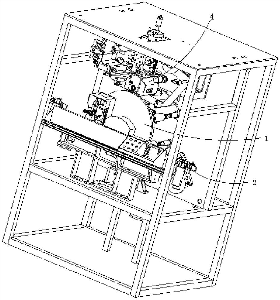
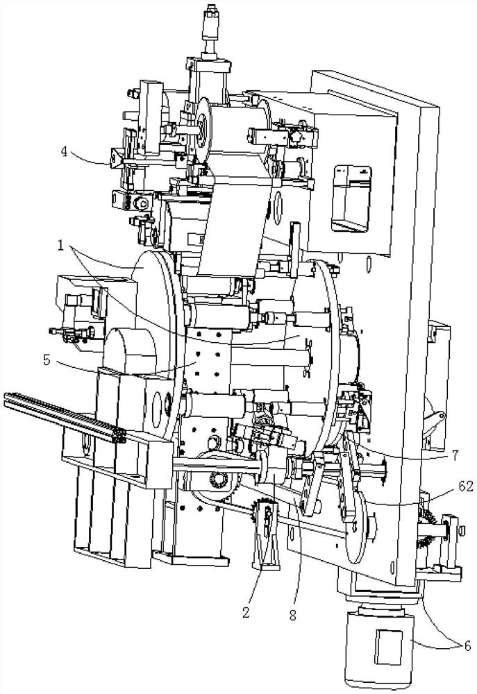
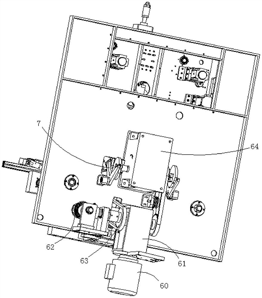
[0029] The thermal transfer equipment of the preferred embodiment of the present invention, such as figure 1 shown, see also Figure 2-8 , including a rotatable tooling turntable assembly 1, a plurality of workpiece clamping units 10 are arranged on the rotating axis of the tooling turntable assembly 1; one side of the tooling turntable assembly 1 is provided with a workpiece clamping unit 10 fa...


PUM


Abstract

The invention relates to heat transfer printing equipment. The heat transfer printing equipment comprises a rotatable tool rotary disc assembly, and a plurality of workpiece clamping units are arranged on the tool rotary disc assembly around the rotating axis of the tool rotary disc assembly. One side of the tool rotary disc assembly is provided with a feeding assembly used for feeding workpiecesto the workpiece clamping units on the tool rotary disc assembly, and the other side of the tool rotary disc assembly is provided with a blanking assembly used for blanking the workpieces from the workpiece clamping units on the tool rotary disc assembly. A heat transfer printing assembly used for printing the workpieces on the tool rotary disc assembly is arranged above the tool rotary disc assembly. The heat transfer printing equipment further comprises a liftable supporting assembly for supporting the workpieces on the tool rotary disc assembly during printing, and a driving mechanism for driving the feeding assembly, the blanking assembly, the tool rotary disc assembly and the supporting assembly. The heat transfer printing equipment further comprises a first output unit for triggeringthe multiple workpiece clamping units at the lower end of the tool rotary disc assembly to loosen the workpieces. The structure is reasonable and compact, the machining efficiency is high, and synchronous control over feeding, blanking and heat transfer printing is extremely convenient.

Description

technical field [0001] The invention relates to the technical field of heat transfer printing, and more specifically, relates to a heat transfer printing device and a method thereof. Background technique [0002] Thermal transfer printing is a new type of printing process. Its printing has the advantages of rich pattern layers, bright colors, ever-changing, small color difference, and good reproducibility. It can meet the requirements of the designer and is suitable for mass production; currently used Thermal transfer equipment, the structural design is unreasonable, and the processing efficiency is low. Contents of the invention [0003] The technical problem to be solved by the present invention is to provide a heat transfer equipment and method thereof in view of the above-mentioned defects of the prior art. [0004] The technical solution adopted by the present invention to solve its technical problems is: [0005] Construct a kind of thermal transfer printing equipm...

Claims


Application Information

Patent Timeline
Patent Type & Authority Applications(China)
IPC IPC(8): B41F16/00B65G47/90
CPCB41F16/00B65G47/907
Inventor 何小辉
Owner 深圳市鑫众塑料包装机械有限公司
Learn More