
Tower type aerobic reactor

An aerobic reactor and tower-type technology, applied in aerobic process treatment, chemical instruments and methods, sustainable biological treatment, etc. Large pool area and other problems, to achieve high treatment capacity, high oxygen utilization rate, high water depth effect

Pending Publication Date: 2020-09-29
苏沃特环境(江苏)有限公司
View PDF0 Cites 0 Cited by
  • Summary
  • Abstract
  • Description
  • Claims
  • Application Information

AI Technical Summary

Problems solved by technology

[0003] Traditionally, the aerobic pool uses a blower to supply air to the aerobic pool. Generally, the wind pressure of the fan is about 5-6m, and the effective water depth of the aerobic pool is about 4-5m. If the wind pressure is lower than 5m, the air and oxygen provided by the fan will The utilization rate will be low; if it exceeds 6m, the wind pressure of the fan will be high and the power of the fan will be high, resulting in a large energy consumption of the aerobic pool; traditionally, the depth of the aerobic pool is 5-6m, resulting in The aerobic pool occupies a large area
[0004] In order to reduce the floor area of ​​the aerobic tank, a tower-type aerobic tank is used, and the height of the tower is 14-16m. Such a tall tower-type aerobic reactor generally adopts a high-pressure method with two-stage fans connected in series to supply air to the aerobic tank. , the series connection of high-pressure fans results in a doubling of the energy consumption of the aerobic reactor

Method used


Image

  • Tower type aerobic reactor

Examples


Embodiment Construction

[0018] The specific embodiments of the present invention will be further described below in conjunction with the accompanying drawings. It should be noted here that the descriptions of these embodiments are used to help understand the present invention, but are not intended to limit the present invention. In addition, the technical features involved in the various embodiments of the present invention described below may be combined with each other as long as they do not constitute a conflict with each other.

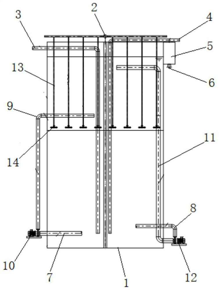
[0019] see figure 1 , the present invention provides a tower aerobic reactor, comprising: a body 1 and an aeration main pipe 2, the top of the body 1 is provided with a water inlet pipe 3, a return sludge pipe 4 and an outlet weir 5; the water inlet pipe 3 and the return sludge pipe 4 extend to the bottom of the body 1; the outlet weir 5 is provided with an outlet pipe 6; the bottom of the body 1 is provided with a nitrifying liquid inlet pipe 7 and a sludge outlet pipe...


PUM


Abstract

The invention discloses a tower type aerobic reactor which comprises a body and an aeration header pipe, and a water inlet pipe, a return sludge pipe and an effluent weir are arranged at the top of the body; the water inlet pipe and the return sludge pipe extend to the bottom of the body; a water outlet pipe is arranged on the effluent weir; a nitrification liquid inlet pipe and a sludge outlet pipe are arranged at the bottom of the body; a nitrification liquid outlet pipe is arranged between the nitrification liquid inlet pipe and the water inlet pipe, and the nitrification liquid outlet pipeand the nitrification liquid inlet pipe are respectively connected with a nitrification liquid internal circulation pump; a sludge inlet pipe is arranged between the sludge outlet pipe and the returnsludge pipe, and the sludge inlet pipe and the sludge outlet pipe are respectively connected with a sludge internal circulation pump; an aeration branch pipe is arranged on the aeration header pipe,and a liftable aerator is arranged at the end part of the aeration branch pipe; and the aeration branch pipes extend into the body from the top of the body. By the arrangement, high water depth, highoxygen utilization rate, high treatment capacity, sufficient contact reaction and low energy consumption can be realized.

Description

technical field [0001] The invention relates to the technical field of sewage treatment devices, in particular to a tower-type aerobic reactor. Background technique [0002] Wastewater aerobic biological treatment technology has long been introduced into China as a traditional but effective sewage treatment process and is frequently used in the field of sewage treatment. Its evolution forms are also diverse, such as SBR, CASS, biological contact oxidation , oxidation ditch, etc., combined with other equipment can also form a traditional sewage treatment process, such as A / O, A 2 / O, etc., of course, it is widely used as an independent unit for sewage treatment, but no matter what form or combination mode, the most important thing in aerobic biological treatment process is residence time, oxygen utilization rate, substrate and sewage The mixing degree of the mud is several factors. [0003] Traditionally, the aerobic pool uses a blower to supply air to the aerobic pool. Gen...

Claims


Application Information

Patent Timeline
IPC IPC(8): C02F3/12C02F3/20
CPCC02F3/1236C02F3/20C02F2301/043Y02W10/10
Inventor 徐富
Owner 苏沃特环境(江苏)有限公司
Learn More