Tuyere gas leakage preventing structure and tuyere sleeve structure

A technology of gas leakage and tuyere cover, applied in the direction of the tuyere, can solve the problems of easily deformed tuyere gas, leakage, complicated manufacturing and installation, etc., and achieves the effect of simple structure, prevention of gas leakage, and guarantee of safety.

Pending Publication Date: 2020-09-29
MCC CAPITAL ENGINEERING & RESEARCH
View PDF0 Cites 0 Cited by
  • Summary
  • Abstract
  • Description
  • Claims
  • Application Information

AI Technical Summary

Problems solved by technology

[0004] The object of the present invention is to provide a structure and a tuyere sleeve structure for preventing gas leakage at the tuyere, to overcome the problems of complex manufacture and installation, easy deformation, and easy gas leakage at the tuyere in the prior art. It is sealed with a conical surface and a sealing ring, which can effectively prevent gas leakage in the tuyere area and ensure the safety of the tuyere area. It is an effective means to achieve low energy consumption and safe production of blast furnaces

Method used


Image

  • Tuyere gas leakage preventing structure and tuyere sleeve structure
  • Tuyere gas leakage preventing structure and tuyere sleeve structure
  • Tuyere gas leakage preventing structure and tuyere sleeve structure

Examples


Embodiment Construction

[0037] In order to have a clearer understanding of the technical features, objectives and effects of the present invention, specific embodiments of the present invention will now be described with reference to the accompanying drawings.

[0038] The specific embodiments of the present invention described herein are only used to explain the purpose of the present invention, and cannot be construed as limiting the present invention in any way. Under the teaching of the present invention, the skilled person can conceive any possible modifications based on the present invention, and these should be regarded as belonging to the scope of the present invention. It should be noted that when an element is referred to as being "disposed on" another element, it may be directly on the other element or a central element may also exist. When an element is considered to be "connected" to another element, it can be directly connected to the other element or an intermediate element may be present...


PUM


Abstract

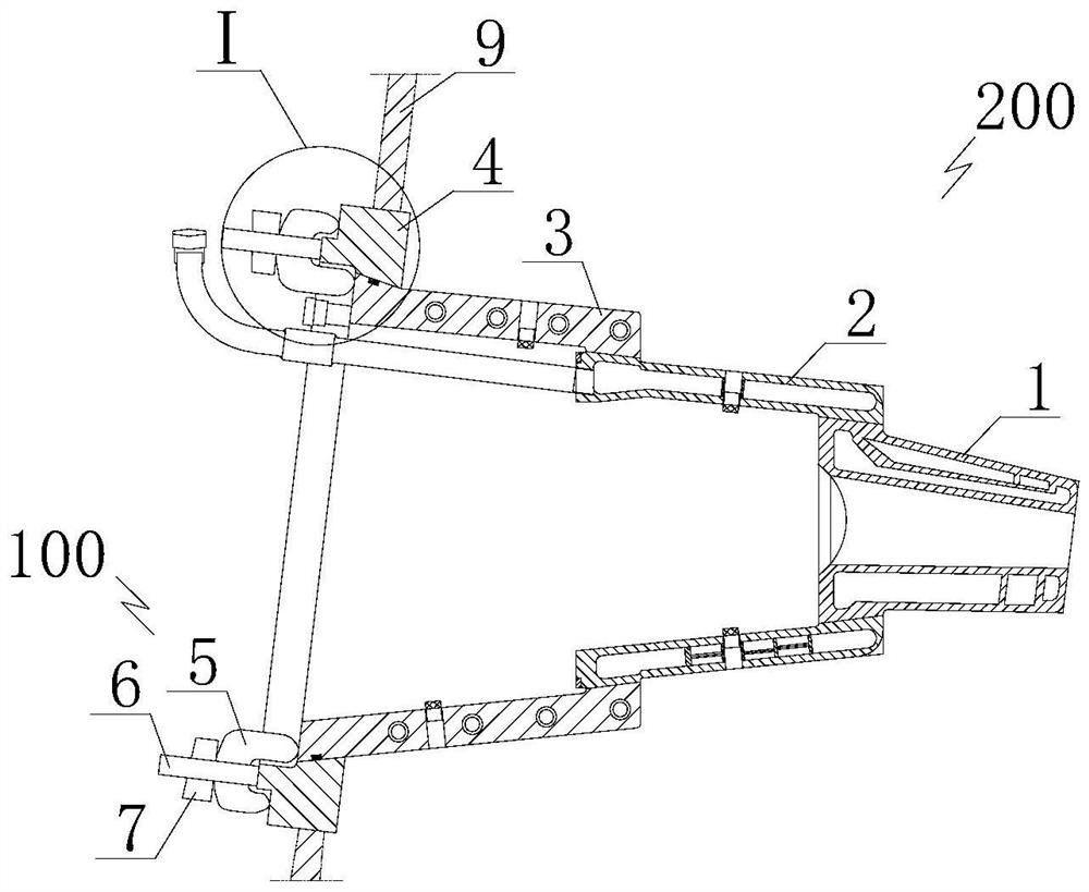
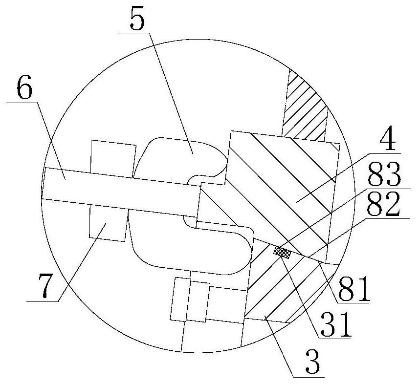
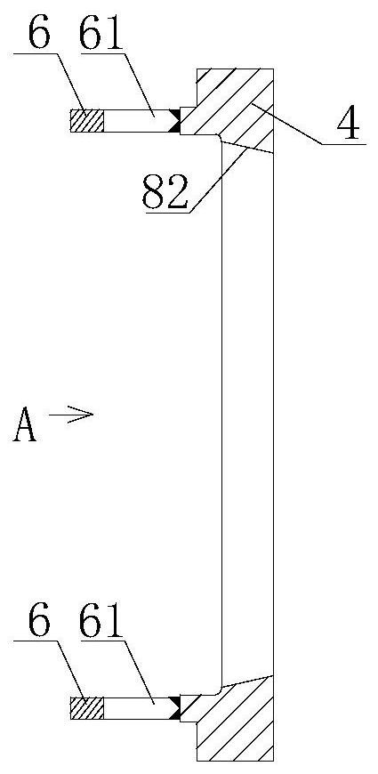
The invention discloses a tuyere gas leakage preventing structure and a tuyere sleeve structure. The tuyere gas leakage preventing structure comprises a plurality of pressing plates, each pressing plate comprises a bent plate part arranged between a tuyere large sleeve and a flange in a spanning mode, first ejecting plate parts capable of abutting against the end faces of the flanges are arrangedon one ends of the bent plate parts, second ejecting plate parts capable of abutting against the end faces of the tuyere large sleeve are arranged on the other ends of the bent plate parts, the tuyeregas leakage preventing structure further comprises outer conical surfaces arranged on the outer wall of the tuyere large sleeve and inner conical surfaces arranged on the inner walls of the flanges,the outer conical surfaces can abut against the inner conical surfaces in a sealed mode, and sealing rings are arranged between the outer conical surfaces and the inner conical surfaces. According tothe tuyere gas leakage preventing structure and the tuyere sleeve structure, the problems that in the prior art, manufacturing and mounting are complex, deformation is likely to happen, and tuyere gasleakage is likely to happen are solved, the tuyere large sleeve and the flanges are connected through the pressing plates, the conical surfaces and the sealing rings are adopted for sealing, gas leakage of the tuyere area can be effectively prevented, the safety of the tuyere area is guaranteed, and the tuyere gas leakage preventing structure and the tuyere sleeve structure are effective means for realizing low-consumption and safe production of a blast furnace.

Description

Technical field [0001] The invention relates to the technical field of iron and steel metallurgy, in particular to a structure for preventing gas leakage from a tuyere and a tuyere sleeve structure. Background technique [0002] During the blast furnace smelting process, hot air enters the furnace through the air supply device and burns at the front end of the tuyere. During combustion, a large amount of high-temperature gas is generated and a whirling zone is formed. The traditional large tuyere sleeve and the flange are connected by bolts. The large sleeve and the flange need to be matched with bolt holes. In order to ensure the reliability of the connection between the two, more bolts are required, and the manufacturing and installation are more complicated. The rigidity is large, and it is prone to deformation during manufacturing and installation. In addition, the two are sealed by metal gaskets. Once the gasket has problems such as aging, it is easy to cause gas leakage. ...

Claims


Application Information

Patent Timeline
IPC IPC(8): C21B7/16
CPCC21B7/16
Inventor 王春龙全强祁四清段国建陈秀娟赵艳霞李平潮
Owner MCC CAPITAL ENGINEERING & RESEARCH
Why Eureka
Try Eureka