Mechanical automatic control range constant pressure purge valve

A mechanical, unblocking valve technology, applied in the direction of mechanical equipment, valve devices, valve details, etc., can solve the problems of being unsuitable for long-distance transportation systems, high cost, and unable to adapt to the working environment

Active Publication Date: 2021-05-14
SUZHOU BATAO INFORMATION TECH CO LTD
View PDF5 Cites 0 Cited by
  • Summary
  • Abstract
  • Description
  • Claims
  • Application Information

AI Technical Summary

Problems solved by technology

[0002] During the material conveying process, especially at the front end of the valve, when the valve is closed, it is easy to accumulate material there. When the valve is opened again, due to the compression of the material, it will be blocked at the front end of the valve, resulting in blocked pipes. Most of the current solutions to the problem of blocked pipes are in the A high-pressure blow-assisted valve connected to the pipeline is installed on the material conveying pipeline. When the pipe is blocked, the device instantly fills a large amount of high-pressure gas into the conveying pipeline to blow away the blocked material and make the pipe unblocked. Both require an independent detection device to detect the phenomenon of material blockage and increase the pressure in time, and to control the blowing of high-pressure gas to remove the blockage. However, the above-mentioned method requires electrical components for detection and control, and may not be able to adapt to the harsh working environment. Therefore, The invention with the application number CN201510840704.4 provides a pneumatic automatic dredging valve, which has the advantages of simple structure and convenient processing and assembly, but this solution still needs to use an external booster device for boosting, and needs to be equipped with a separate booster pipeline, etc. , not only the cost is high, but also not suitable for use in long-distance transportation systems

Method used


Image

  • Mechanical automatic control range constant pressure purge valve
  • Mechanical automatic control range constant pressure purge valve
  • Mechanical automatic control range constant pressure purge valve

Examples


Embodiment Construction

[0030]Next, the technical solutions in the embodiments of the present invention will be apparent from the embodiment of the present invention, and it is clearly described, and it is understood that the described embodiments are merely embodiments of the present invention, not all of the embodiments. Based on the embodiments of the present invention, there are all other embodiments obtained without making creative labor without making creative labor premises.

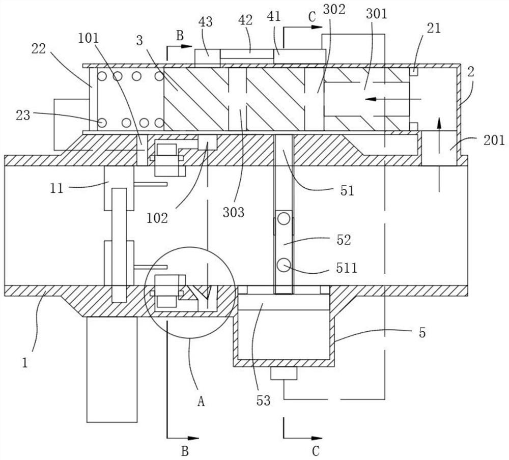
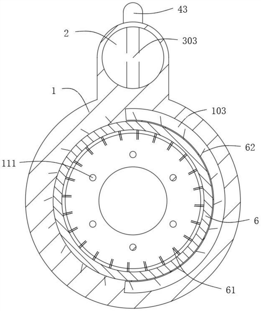
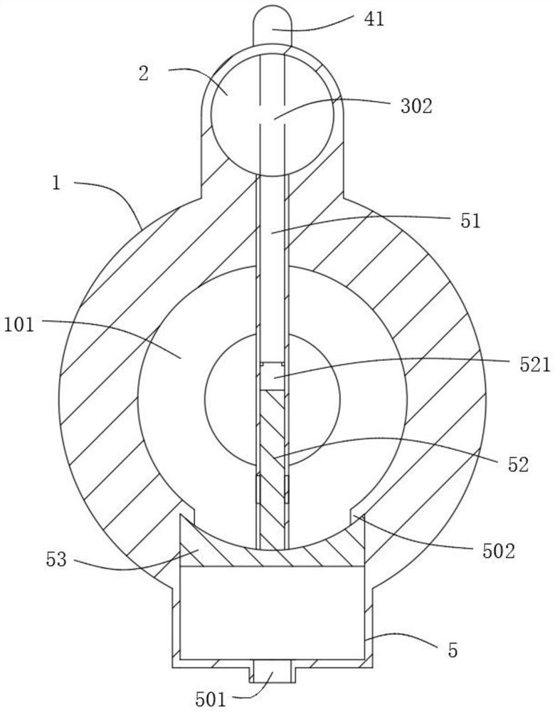
[0031]Example:Figure 1 ~ 6 As shown, the mechanical automatic control range is fixed, including the valve 11 mounted in the conveying conduit 1, and the pressure cylinder 2 is mounted on the outer wall of the conveying conduit 1, and the pressure cylinder 2 is provided with pressure and along axial direction. The moving active plug 3, one end of the pressure cylinder 2 communicates with the conveying conduit 1 through the intake chamber 201, the intake chamber 201 is at least 30 cm from the valve 11, and the intake cavity 201 is ...


PUM


Abstract

The invention relates to the technical field of material conveying valves, in particular to a range constant pressure dredging valve with mechanical automatic control, including a valve installed in a conveying pipeline, a pressure cylinder is installed on the outer wall of the conveying pipeline, and a pressure cylinder is installed in the pressure cylinder There is a movable plug that moves axially under pressure, and one end of the pressure cylinder communicates with the delivery pipeline through an air intake cavity, and the air intake cavity is at least 20cm away from the valve; the present invention utilizes the pressure difference of the delivery pipeline itself , to make the movable plug move, and use the pressure at the far end of the pipeline to drive the dredging component, use the volume increasing component to increase the volume of the blocked space, and use the booster component and the agitating component to stir and fragment the blocked place, and fill To increase the capacity of the space, the dense material at the blockage is gradually loosened, and can flow through the valve, and dredging can be completed without a large external pressurization. After dredging, the fragmentation effect of the blockage is good, reducing the subsequent plugging probability.

Description

Technical field[0001]The present invention relates to the technical field of material delivery valve, and is specifically a row of mechanical automatic control.Background technique[0002]The material is in particular in the front end of the valve, and the valve is closed when the valve is closed. When the valve is turned on, due to the compression of the material, it is blocked in the front end of the valve, causing a plugging, and the method of solving the problem of plugging the problem is mostly The high-pressure blowout of the pipe communication is installed on the material delivery conduit. When the pipe is plugging, the device instantly charges a large number of high pressure gas into the conveying pipe, to blow away the material, so that the tube is smooth, and now help the gover There is a separate detection device to achieve timely detection of material blocking pipe to increase the pressure, and control high pressure gas blowing into the drainage, but the above-described ma...

Claims


Application Information

Patent Timeline
Patent Type & Authority Patents(China)
IPC IPC(8): F16L55/24F16L55/07B08B9/032B02C19/06
CPCB02C19/06B08B9/0325F16K27/00F16K37/0091F16L55/07F16L55/24
Inventor 王凤明
Owner SUZHOU BATAO INFORMATION TECH CO LTD
Why Eureka
Try Eureka