
Pump base of lubricating pump and lubricating pump

A technology for lubricating pumps and pump bases, used in lubrication pumps, lubricating parts, engine lubrication, etc., can solve problems such as low exhaust efficiency, and achieve the effect of improving exhaust efficiency and reducing air content

Pending Publication Date: 2020-09-29
AUTOL TECH
View PDF1 Cites 0 Cited by
  • Summary
  • Abstract
  • Description
  • Claims
  • Application Information

AI Technical Summary

Problems solved by technology

[0004] The purpose of the present invention is to provide a lubricating pump pump base to solve the technical problem of low exhaust efficiency when the pump base fills the oil tank with grease; the purpose of the present invention is also to provide a lubricating pump using the lubricating pump pump base , to solve the technical problem of low exhaust efficiency when adding grease to the lubrication pump

Method used


Image

  • Pump base of lubricating pump and lubricating pump
  • Pump base of lubricating pump and lubricating pump
  • Pump base of lubricating pump and lubricating pump

Examples


Embodiment Construction

[0030] Embodiments of the present invention will be further described below in conjunction with the accompanying drawings.

[0031] The specific embodiment of lubricating pump of the present invention:

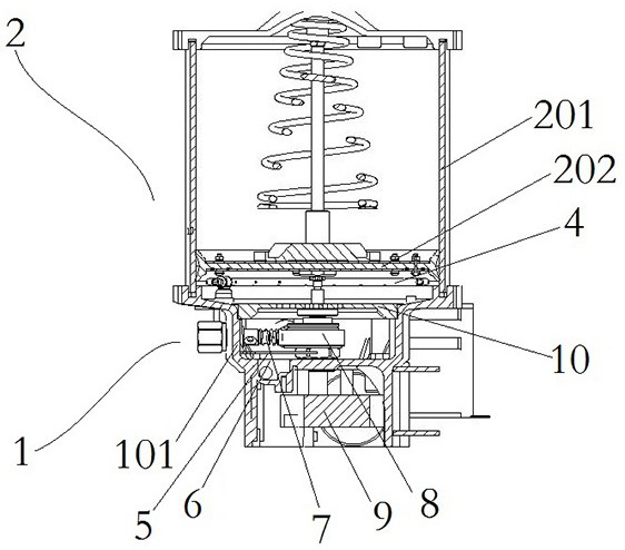
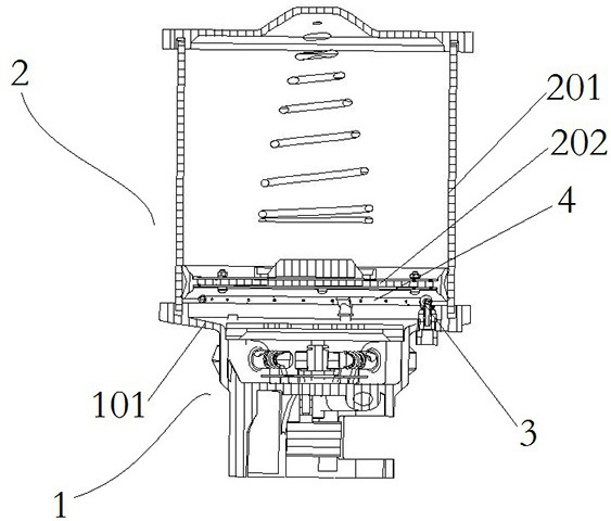
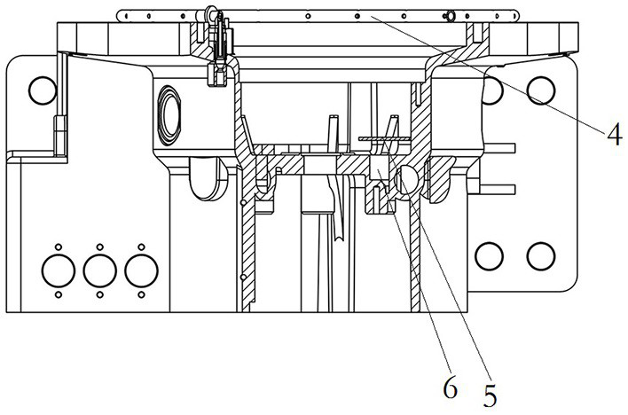
[0032] Such as Figure 1 to Figure 6 As shown, the lubricating pump includes a lubricating pump base 1 and an oil tank 2 fixed on the lubricating pump base 1. The upper side of the lubricating pump base 1 has a base 101, and the base 101 and the oil tank 2 form a sealed oil chamber. The bottom of the seat body 101 is provided with an oil filling port 6 communicating with the oil chamber for filling oil into the oil chamber.

[0033] The base body 101 is also provided with a horizontal deflector 5, the deflector 5 covers the top of the oil filling port 6, and the deflector 5 is spaced from the bottom wall of the base 101 to form a flow guide channel for the grease to spread horizontally. . The base body 101 is provided with an exhaust passage communicating with the outside w...


PUM


Abstract

The invention relates to the technical field of lubricating equipment, and in particular relates to a pump base of a lubricating pump and the lubricating pump. The lubricating pump comprises the pumpbase and an oil tank, wherein the pump base comprises a base body, a sealed oil cavity is defined by the base body and the oil tank, an oil filling orifice is formed in the bottom of the base body, the oil filling orifice has the upward opening and is eccentrically arranged, an exhaust channel is arranged in the oil tank or the base body, and a flow guide plate is arranged in the base body. When oil is injected into the lubricating pump, after the grease enters the oil cavity in the upper portion of the base body from the oil filling orifice, the grease first moves to the position far away from the oil filling orifice in the horizontal direction under pressing of the flow guide plate so as to horizontally spread, then the grease in the oil cavity is wholly lifted, therefore, the grease inthe oil cavity can better drive air in the base body upwards in the accumulation and rising process, and the air is exhausted to the outside through the exhaust channel. In this way, the air content in the grease entering the oil tank is effectively reduced, and then the lubricating effect of the lubricating pump is improved.

Description

technical field [0001] The invention relates to the technical field of lubricating equipment, in particular to a lubricating pump base and a lubricating pump. Background technique [0002] As a kind of lubrication equipment, the lubrication pump is mainly used for regular lubrication of mechanical equipment to reduce the frictional resistance between mechanical equipment and slow down wear. The lubrication pump usually includes an oil tank and a pump seat, and the pump seat includes a seat body and a pump core assembly , the grease in the oil tank is transported to the lubricated part through the pump core assembly for lubrication. For example, the Chinese utility model patent document with the authorized announcement number CN207162089U discloses a pump core assembly for an electric lubrication pump. The pump core assembly includes a pump core Body, plunger, eccentric shaft, shaft sleeve and motor, the plunger is movably assembled on the pump core body, the eccentric shaft ...

Claims


Application Information

Patent Timeline
IPC IPC(8): F16N13/02F16N13/06F16N39/00
CPCF16N13/02F16N13/06F16N39/002F16N2013/063
Inventor 闫进旺赵民章李建华刘彦菲李宏志
Owner AUTOL TECH
Learn More