Three-dimensional head-mounted microscope

A head-mounted, microscope technology, used in microscopes, optics, instruments, etc., can solve the problems of complex shape of optical components, large loss, blocking imaging area, etc.

Pending Publication Date: 2020-09-29
苏州溢博伦光电仪器有限公司
View PDF0 Cites 2 Cited by
  • Summary
  • Abstract
  • Description
  • Claims
  • Application Information

AI Technical Summary

Problems solved by technology

Due to the large dispersion of the scattering angle of the fluorescent photons, the multiple reflection paths of the fluorescent photons after entering the additional collection optical path are complicated and the loss is large, which limits the actual collection efficiency of the additional optical elements
In addition, the shape of the additional optical components is complex, the processing is very difficult, and the cost is also high
Many of the above-mentioned techniques for enhancing fluorescence collection efficiency are too bulky and will block the imaging area, hindering the simultaneous operation of electrophysiological experiments
[0005] In addition, in mouse experiments, microscopes are often used to detect the activities of experimental mice and certain indicators of mouse biological tissues. Both are relatively large, so they cannot be worn on the head of the mouse, and some indicators such as the activity and biological tissue of the mouse cannot be detected in real time, and the operation is very inconvenient

Method used


Image

  • Three-dimensional head-mounted microscope
  • Three-dimensional head-mounted microscope
  • Three-dimensional head-mounted microscope

Examples


Embodiment 1

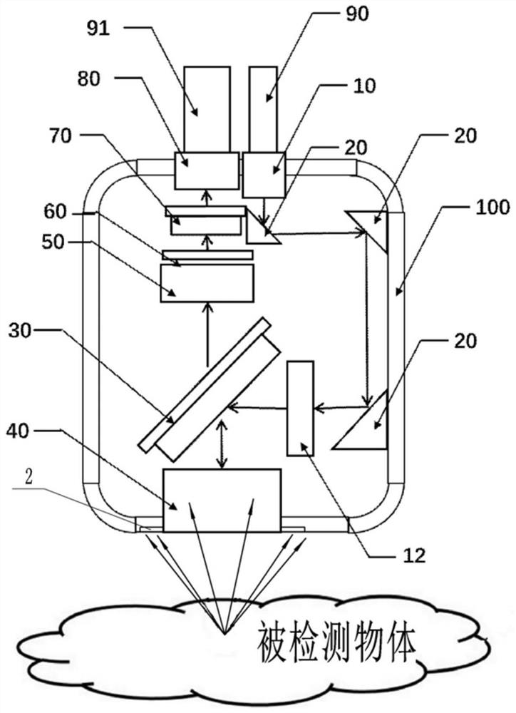
[0031] Basic as attached figure 1 Shown: a three-dimensional head-mounted microscope, including a square housing 100, the housing 100 is a sealed structure made of a high molecular polymer material, and a collimating lens 10, a cylindrical lens 12, a reflector 20, and a dichroic lens are installed in the housing 100 Chromatic mirror scanner 30, objective lens 40, focusing lens 50, wave plate 60, vertical dichroic mirror scanner 70 and collecting lens 80, specifically, for the installation method, it can be bonded, clamped, bonded or welded . combine Figure 5 with Image 6 As shown, the dichroic mirror scanner 30 in this embodiment includes 33 dichroic mirrors and a microelectromechanical driver 22 that does not affect the transmission of nonlinear optical signals. The 33 dichroic mirrors are covered on the microelectromechanical driver 22. The MEMS driver 22 can drive the dichroic mirror 33 to change the angle. Object lens 40 is an aspherical lens in the present embodimen...

Embodiment 2

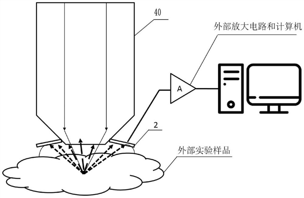
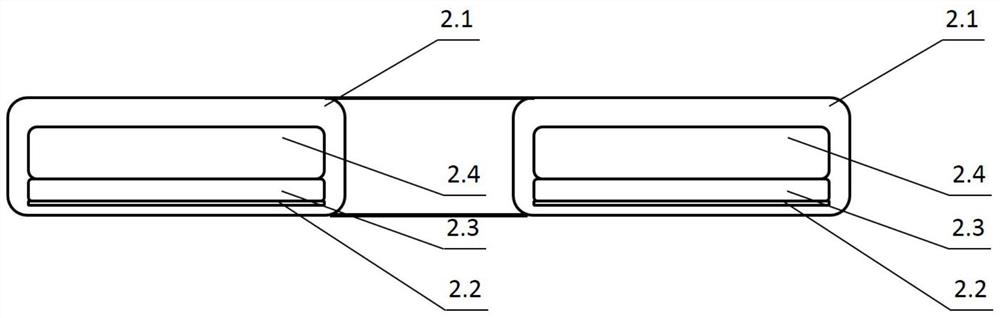
[0049] In the present embodiment, the photosensitive unit 2.3 of the photodetector 2 is formed into an annular array by a plurality of ordinary size avalanche diodes (Avalanche Photo Diode, LAAPD). Chips of common-sized avalanche diodes are used to receive fluorescent photons that cannot be picked up by microscope objectives.

Embodiment 3

[0051] The photosensitive unit 2.3 of the photodetector 2 among the present embodiment is formed ring array by two-dimensional pixel photosensor, as CCD (photoelectric coupling device) device, CMOS (metal semiconductor oxide) device, FPA (focal plane array) device, PMT (photomultiplier tube) device, single photon counting device or hybrid device based on any of the above multiple photoelectric conversion principles, such as Hamamatsu's hybrid photodetector (HPD), the central hole or transparent material is used to pass through the microscope objective An annular array of two-dimensional pixel photosensors is used to receive the fluorescent photons that cannot be received by the microscope objective.


PUM

PropertyMeasurementUnit
dielectric strengthaaaaaaaaaa
wavelengthaaaaaaaaaa

Abstract

The invention relates to the technical field of optical microscopic imaging, and in particular relates to a three-dimensional head-mounted microscope which comprises a lens assembly, an objective lensand a scanner assembly. A photoelectric detector is arranged on the objective lens and comprises a protection element, an optical filter, a photoelectric sensitive unit and a driving circuit. According to the scheme, related elements for fluorescence collection are simplified, so that the sizes of the related elements for fluorescence collection are smaller, and meanwhile, related experimental operation and detection can be carried out.

Description

technical field [0001] The invention relates to the technical field of optical microscopic imaging, in particular to a three-dimensional head-mounted microscope. Background technique [0002] In nonlinear optical imaging microscopy, especially in multiphoton fluorescence microscopy, near-infrared laser pulses are focused by the microscope objective to excite isotropic emission of fluorescence signals in the sample. Biological tissue usually exhibits strong absorption and high scattering optical properties. For epifluorescence fluorescence detection, the same microscope objective is used both to focus the excitation light and to collect the fluorescence signal. The intensity of the fluorescent signal collected by the microscope objective depends on the numerical aperture of the microscope objective and the objective front aperture (Objective Front Aperture, OFA) (E.Beaurepaire, et.al, AppliedOptics, vol.41, no.25, pp. 5376-5382, 2002). The larger the numerical aperture of ...

Claims


Application Information

Patent Timeline
Patent Type & Authority Applications(China)
IPC IPC(8): G02B21/02G02B21/00
CPCG02B21/00G02B21/02
Inventor 不公告发明人
Owner 苏州溢博伦光电仪器有限公司
Why Eureka
Try Eureka