Printing machine

A printing machine and printing technology, applied to printing machines, rotary printing machines, screen printing machines, etc., can solve the problems of reduced service life of the machine, easy generation of waste, repeated positioning, etc., to achieve enhanced service life, guaranteed effect, and accelerated The effect of dry molding

Pending Publication Date: 2020-10-02
丁帅飞
View PDF6 Cites 4 Cited by
  • Summary
  • Abstract
  • Description
  • Claims
  • Application Information

AI Technical Summary

Problems solved by technology

[0005] Existing printing machines, whether they are flat screen printing machines or rotary screen printing machines, generally include a screen assembly, a magnetic table arranged under the screen assembly, and a printing guide belt arranged between the screen assembly and the magnetic table. The magnetic bar in the screen assembly is adsorbed on the fabric on the printing guide belt, and the magnetic bar is driven to move on the screen assembly through the magnetic table to realize printing. On the table, when the magnetic table is uneven or the magnetic table’s adsorption force on the magnetic rod changes, the pressure of the magnetic rod on the cloth will change, which will make the printing on the cloth uneven and the printing quality poor. First, the gray cloth is passed through the cloth feeding device, then sent to the printing device for printing, and finally rolled up and placed, and the cloth is directly placed on the workbench for printing. The cloth is prone to offset during the winding process, making the printing positioning inaccurate. Repeated positioning is required, which makes the printing machine low in efficiency and high in labor costs; during the printing process, the fabric is easy to wrinkle, and waste is easily generated, resulting in a large waste. In addition, during the printing process, due to the exposure of ink and nozzles, dust will accumulate. Affect the color of the printing and reduce the service life of the machine
[0006] In daily life, various patterns and patterns are printed on our common textile fabrics, clothing, garments, socks and other textiles. The early textile printing was all printed by hand. With the development of science and technology, various This kind of textile printing machinery has gradually replaced manual printing, but there are many shortcomings in the existing printing machines: in the printing process of the printing machine, it is necessary to manually add printing paste to the printing device continuously, and before adding the printing paste It needs to be manually stirred, which is labor-intensive and low-efficiency. After the printed object is printed, it needs to be transported to an oven for drying. Infrared heating tubes are used in the oven. Yes, the yield is low, and the oven occupies a large area; the printing device in the printing machine has a short service life, and the quality of the printing is not high. After drying, it needs to be transported to the cutting device for cutting, and the process is cumbersome complicated, time consuming

Method used


Image

  • Printing machine
  • Printing machine
  • Printing machine

Examples


Embodiment Construction

[0031] The following will clearly and completely describe the technical solutions in the embodiments of the present invention with reference to the accompanying drawings in the embodiments of the present invention. Obviously, the described embodiments are only some, not all, embodiments of the present invention. Based on the embodiments of the present invention, all other embodiments obtained by persons of ordinary skill in the art without making creative efforts belong to the protection scope of the present invention.

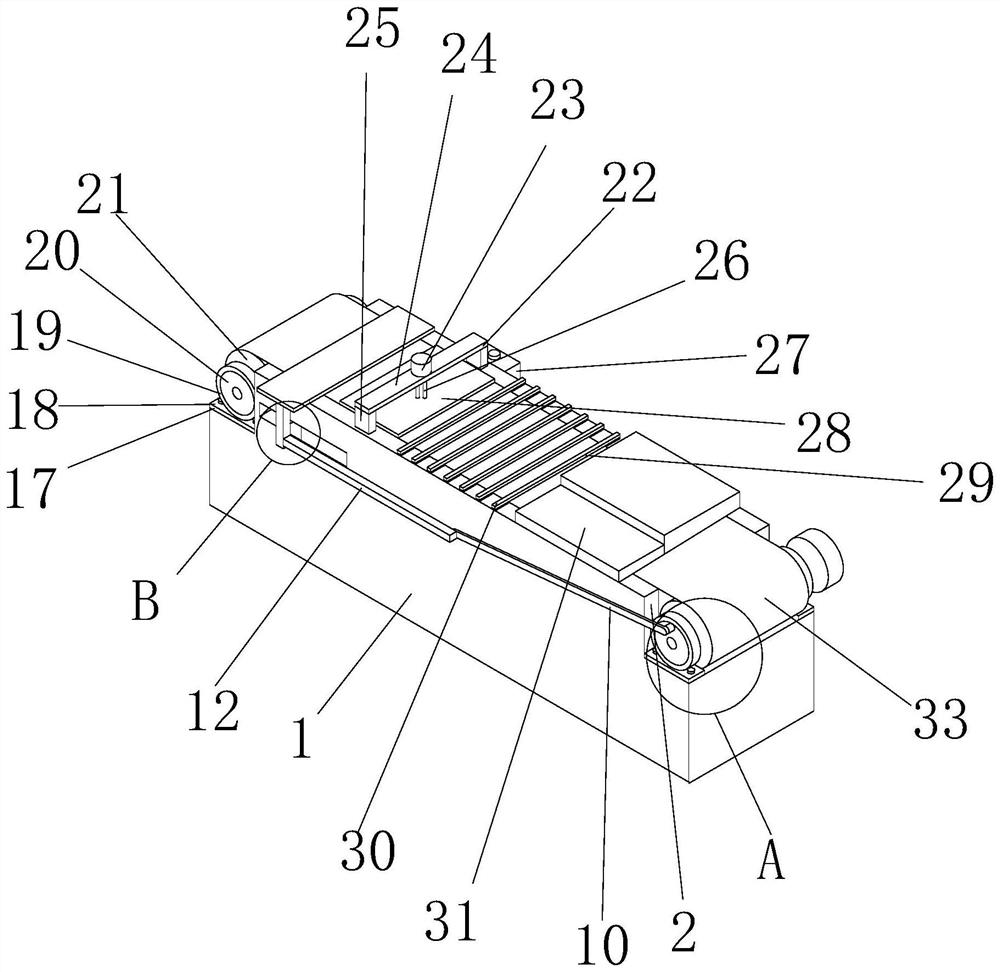
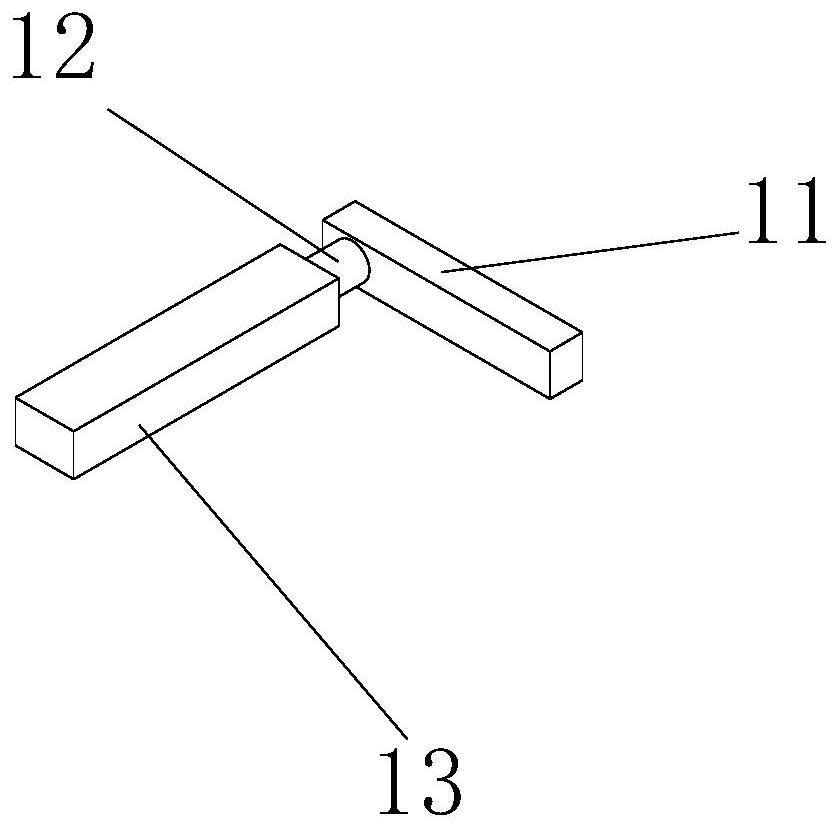
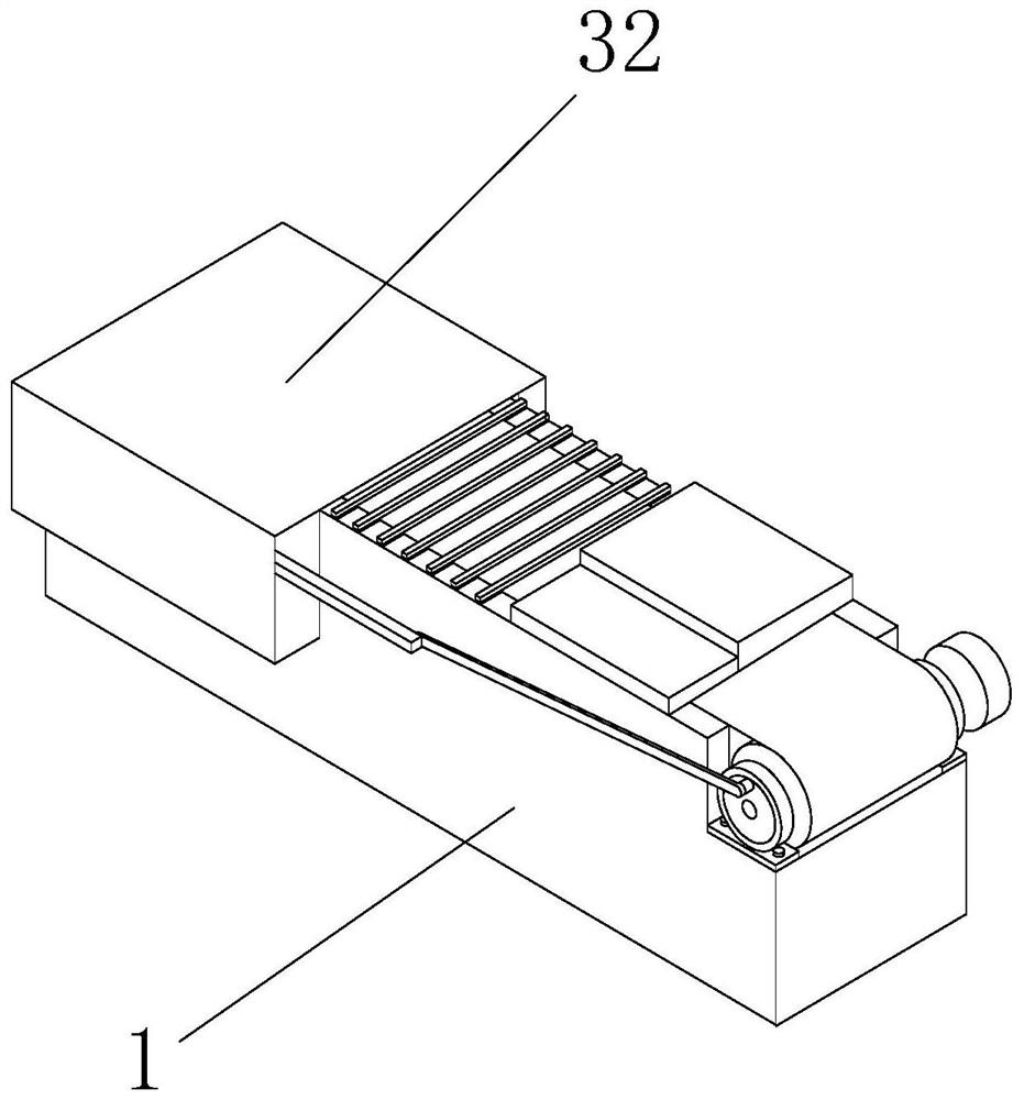
[0032] see Figure 1-4 , the present invention provides a technical solution: a printing machine, a printing machine, including a body 1, a gap-2 is opened in the upper right corner of the body 1, a fixed plate-3 is fixedly connected to the lower surface of the gap-2, and a fixed plate-3 The left and right ends are fixedly connected with screws 4, the upper part of the fixed plate-3 is fixedly connected with a snare-5, the inside of the snare-5 is sleeved with...


PUM


Abstract

The invention discloses a printing machine, and relates to the technical field of printing machines. According to the printing machine, a fixing column is fixedly connected to the rear surface of a first bearing; a connecting rod is fixedly connected to the right end of the fixing column; a rotating column is connected to the rear surface of the left end of the connecting rod in a sleeving mode; asliding strip is connected to the interior of the front end of the rotating column; a vertical plate is fixedly connected to the left end of the sliding strip; a sliding block is fixedly connected tothe front surface of the vertical plate; a square groove is formed in the rear surface of a box body; and a pressing plate is fixedly connected to the upper end of the vertical plate. According to the printing machine, a motor is started, the first bearing rotates to drive a first roller to rotate, raw cloth can be conveyed clockwise, the sliding strip pushes the sliding block to move left and right in the square groove, the vertical plate drives the pressing plate to move left and right, the raw cloth is repeatedly flattened, so that the raw cloth can be effectively kept flat during feeding,and printing is facilitated; and a heating pipe is arranged at the right end of a printing device, a heat insulation seat is fixedly connected to the lower end of the heating pipe, when the raw clothis conveyed to the position below the heating pipe, printing ink can be uniformly heated, and therefore drying and forming of the ink can be accelerated more effectively.

Description

technical field [0001] The invention relates to the technical field of printing machines, in particular to a printing machine. Background technique [0002] The printing machine is a main equipment for textile printing. Its working principle is: through a cylindrical metal net with a pattern (that is, a circular screen), a pure rolling motion is made on the textile to be printed, so that the dye in the circular screen is scraped Under the pressure of the printing device, the mesh with the patterned rotary screen is transferred to the fabric to complete the printing process of the textile. The cost of the rotary screen printing is low and the processing is convenient. It is currently the most important printing method, but The accuracy of rotary screen printing is poor, and it is not easy to control printing processes such as special burnt-out and engraved printing. When printing some fabrics with special requirements, rotary screen printing is limited by the technical level ...

Claims


Application Information

Patent Timeline
Patent Type & Authority Applications(China)
IPC IPC(8): B41J3/407B41J11/00B41J3/44B41J29/13B41F17/00B41F23/04B41F22/00B41F19/00B41F31/02B41F31/08B65H23/26
CPCB41F17/003B41F19/008B41F22/00B41F23/04B41F31/02B41F31/08B41J3/4078B41J3/44B41J11/002B41J29/13B65H23/26
Inventor 丁帅飞
Owner 丁帅飞
Why Eureka
Try Eureka