Multi-purpose system and method and device using processors of different speeds

A multi-processor system and processor technology, applied in the direction of combining various digital computers, generating/distributing signals, etc., can solve problems such as expensive

Inactive Publication Date: 2003-08-06
IBM CORP
View PDF3 Cites 0 Cited by
  • Summary
  • Abstract
  • Description
  • Claims
  • Application Information

AI Technical Summary

Problems solved by technology

Replacing all processors because...

Method used


Image

  • Multi-purpose system and method and device using processors of different speeds
  • Multi-purpose system and method and device using processors of different speeds
  • Multi-purpose system and method and device using processors of different speeds

Examples


Embodiment Construction

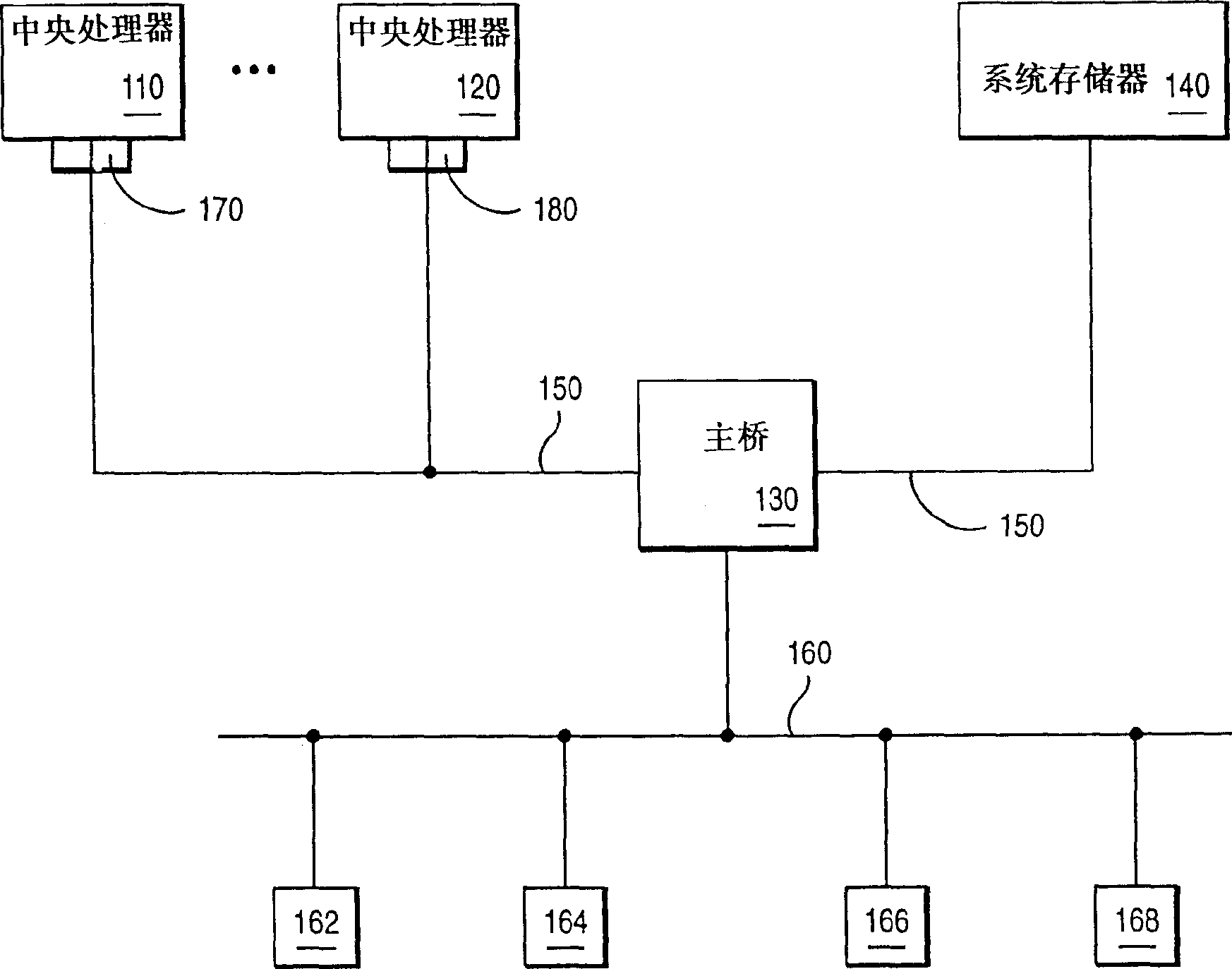
[0012] figure 1 is a block diagram of computer system 100 employed in a preferred embodiment of the present invention. The computer may take the form of a workstation for the RS / 6000 system from IBM Corporation, however, the invention is not intended to be limited thereto but makes it per se equally applicable to any other computer system.

[0013] still on figure 1 In general, the computer system 100 includes a set of central processing units (CPUs) 110 and 120 connected to a system memory 140 via a hast bridge 130 on a system bus 150 . The host bridge is connected to a peripheral component interconnect (PCI) bus 160 with a number of PCI devices 162-168. PCI devices may include the following: graphics adapters, communications adapters, network adapters, optical disks, floppy disks, and hard drives, among others. CPUs 110 and 120 are connected to computer system 100 through connectors 170 and 180, respectively.

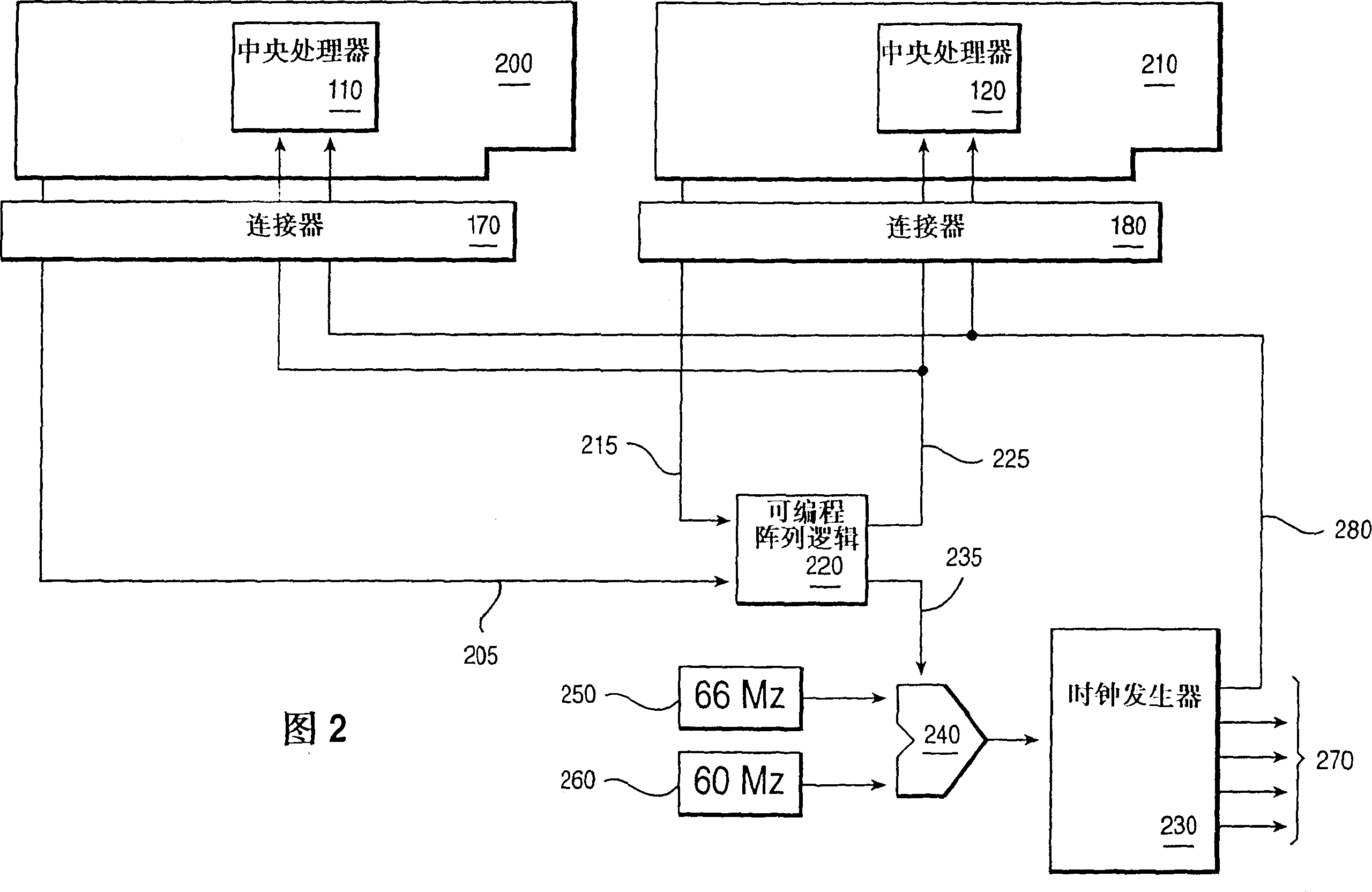
[0014] Fig. 2 is a block diagram of a processor and a circ...


PUM


Abstract

A method and apparatus of allowing processors of different speeds to be used in a multi-processor system are disclosed. The method and apparatus comprise a programmable array logic (PAL) or field programmable gate array (FPGA) that detects each of the processors maximum speed and selects a speed common to all of the processors as the operating speed of the processors. The method and apparatus also adjust the system clock to match the speed of the processors.

Description

technical field [0001] The present invention relates to a multiprocessor system, and more particularly to a multiprocessor system using a plurality of processors with different maximum operating rates. technical background [0002] Many modern computers are symmetric multiprocessor systems. In a symmetric multiprocessor system, each processor is dedicated to performing a specific task. For example, each processor may be used to execute a different instruction set for the same process or an entirely different process, or each processor may be designed to efficiently specialize in certain specific tasks. Therefore, it is conceivable that using more than one processor in a computer system will generally increase the performance of the system. [0003] Some computer manufacturers offer symmetric multiprocessor computer systems with replaceable processors. The processor is usually connected to the motherboard of the computer system through a connector in the form of a pluggabl...

Claims


Application Information

Patent Timeline
IPC IPC(8): G06F1/08
CPCG06F1/08
Inventor 罗纳德·泽维尔·阿罗约克洪·赫·法哈姆
Owner IBM CORP
Why Eureka
Try Eureka