
Pier tail structure of double-conveyance aqueduct

An aqueduct and end pier technology, applied in the field of water transfer safety in water diversion projects, can solve problems such as large fluctuations in water surface, fluctuations in water surface, water overflow in aqueducts and open channels, etc., to improve the water transfer capacity of aqueducts, reduce alternating water loads, The effect of head loss reduction

Pending Publication Date: 2020-10-02
CHANGJIANG RIVER SCI RES INST CHANGJIANG WATER RESOURCES COMMISSION
View PDF5 Cites 0 Cited by
  • Summary
  • Abstract
  • Description
  • Claims
  • Application Information

AI Technical Summary

Problems solved by technology

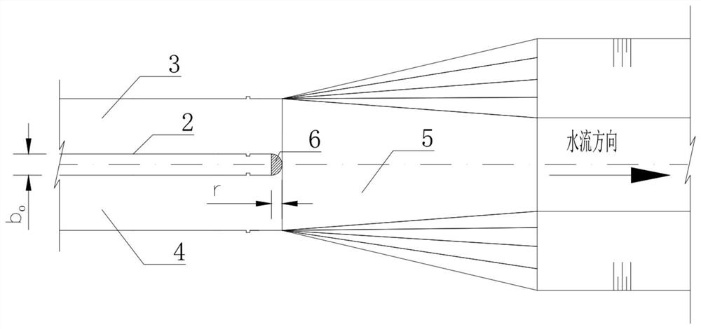
[0004] The inventor of the present application finds through research in the process of realizing the present invention: during the actual operation of the project, the existing design that is positioned at the rear end of the partition wall 2 is a semicircular tail pier 6 (such as image 3 As shown), some aqueducts have large fluctuations in the water surface during large-scale water delivery, and the fluctuations in the water flow in the left and right channels of the aqueduct alternately rise and fall, even causing large fluctuations in the water surface in the open channels upstream and downstream of the aqueduct; and Large fluctuations in water flow may cause the aqueduct and open channel to overflow, reducing the water delivery capacity of the aqueduct and channel where the accident occurred, and even becoming a bottleneck restricting the water delivery capacity of the entire water diversion project. At the same time, the structure of the aqueduct and open channel is safe and slope stability are also threatened, ultimately affecting the comprehensive benefits of the entire water diversion project

Method used


Image

  • Pier tail structure of double-conveyance aqueduct
  • Pier tail structure of double-conveyance aqueduct
  • Pier tail structure of double-conveyance aqueduct

Examples


Embodiment Construction

[0021] The technical solutions in the embodiments of the present invention are clearly and completely described below in conjunction with the accompanying drawings in the embodiments of the present invention. Obviously, the described embodiments are only part of the embodiments of the present invention, not all of them. Based on the embodiments of the present invention, all other embodiments obtained by persons of ordinary skill in the art without making creative efforts belong to the protection scope of the present invention.

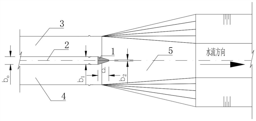
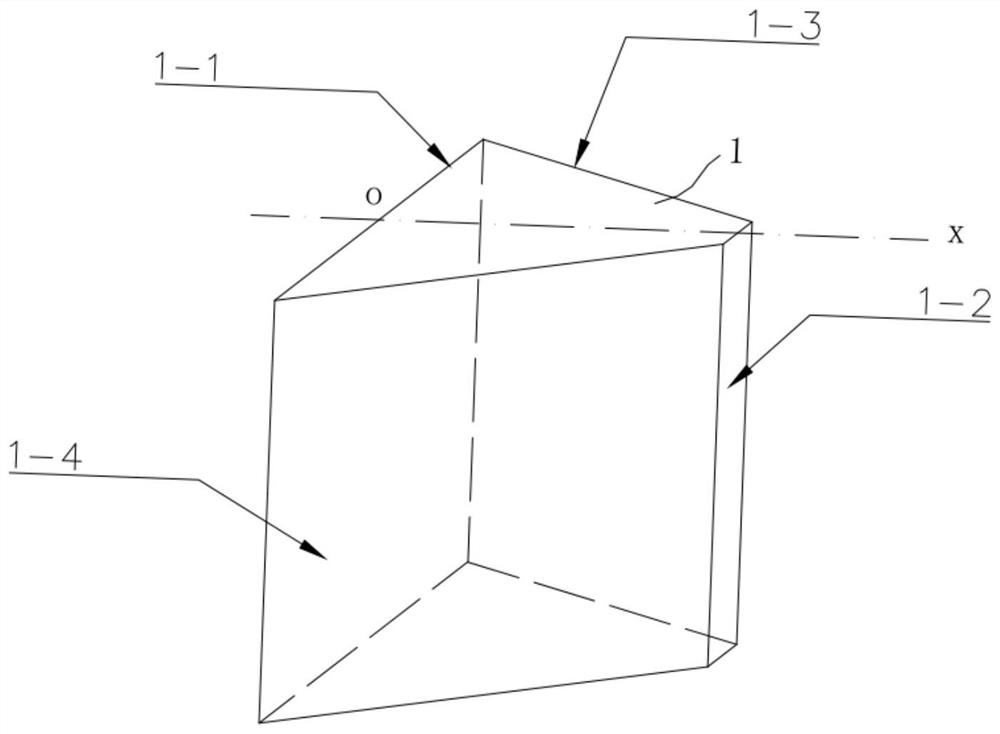
[0022] see figure 1 and figure 2 , one embodiment of the pier tail structure of a double-line water conveyance aqueduct provided by the present invention includes a narrow tail pier 1, a middle partition wall 2, aqueduct left channel 3, aqueduct right channel 4, and open channel transition section 5.

[0023] The narrow end pier 1 is located at the end of the partition wall 2 and is connected with it. The narrow end pier 1 is a symmetrical structure...


PUM


Abstract

The invention provides a pier tail structure of a double-conveyance aqueduct. The pier tail structure comprises a narrow tail pier, a middle partition wall, an aqueduct left ditch, an aqueduct right ditch, an open channel gradual-changing section. The aqueduct left ditch and the aqueduct right ditch are disposed with the central line of the middle partition wall as the symmetry axis. The tail endof the middle partition wall is connected with the narrow tail pier. The narrow tail pier is disposed with the central line of the middle partition wall as the symmetry axis. The middle partition wall, the narrow tail pier and the open channel gradual-changing section are all disposed with the central line of the middle partition wall as the symmetry axis. The widths from the head end to the tailend of the narrow tail pier gradually decrease, so that separation of water flow boundary layers attached to the left and right side walls of the narrow tail pier becomes slow. Compared with a traditional dual-conveyance aqueduct pier tail structure, the pier tail structure can prevent water flow from fluctuating drastically during aqueduct water conveyance, improve stress characteristics of the aqueduct structure and improve the water conveyance capacity of the aqueduct, and has guidance significance in designing the dual-conveyance aqueduct during a water diversion project.

Description

technical field [0001] The invention relates to the field of water transfer safety in water diversion projects, in particular to a pier tail structure of a double-line water transfer aqueduct. Background technique [0002] The construction of water diversion projects is an important way to solve the problem of insufficient regional water resources or uneven distribution of time and space. After the water diversion project is implemented, it can greatly improve the water resource allocation capacity and water supply guarantee capacity of the water receiving area, and the economic, social and ecological environmental benefits. very significant. [0003] In long-distance, cross-basin large-scale water diversion engineering systems, aqueducts are the most commonly used water delivery cross structures, and aqueducts with double lines and double grooves are also common. According to the conventional design method, the upper and lower reaches of the double-line water conveyance aq...

Claims


Application Information

Patent Timeline
Patent Type & Authority Applications(China)
IPC IPC(8): E02B5/00E02B5/08
CPCE02B5/00E02B5/08
Inventor 王才欢侯冬梅段文刚刘爽颜天佑张潮胡清义陈文彬杨芳龚汉忠刘兵龚道勇王英奎林新志刘熙
Owner CHANGJIANG RIVER SCI RES INST CHANGJIANG WATER RESOURCES COMMISSION
Learn More