A three-dimensional stabilizer

A three-dimensional, mandrel technology, applied in the direction of drill pipe, casing, drilling tools, etc., can solve the problems of affecting the life of downhole tools and the uneven force of downhole tools, so as to improve the drilling efficiency, protect the drill bit and improve the drilling efficiency Effect

Active Publication Date: 2022-06-24
HELI TECH ENERGY CO LTD
View PDF11 Cites 0 Cited by
  • Summary
  • Abstract
  • Description
  • Claims
  • Application Information

AI Technical Summary

Problems solved by technology

In addition to the stick-slip phenomenon, sudden changes in formation lithology, bottom-hole pressure fluctuations, mud-carrying efficiency, and ground operations will cause uneven stress on downhole tools and drill bits, and long-term vibration accumulation will affect downhole tool life

Method used


Image

  • A three-dimensional stabilizer
  • A three-dimensional stabilizer
  • A three-dimensional stabilizer

Examples


Embodiment 1

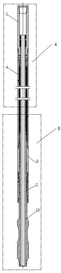
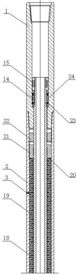
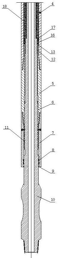
[0016] A three-dimensional stabilizer of the present invention is composed of an upper joint 1, a casing 2 and a mandrel 10. The lower end of the upper joint 1 is connected with the upper end of the casing 2 by a screw thread, and the lower end of the casing 2 is connected with the upper end of the transmission sleeve 5. The screw connection, the lower end of the transmission sleeve 5 is connected with the upper end of the protective sleeve 7 by the screw connection;

[0017] The upper end of the mandrel 10 is placed in the upper joint 1, the upper end thread of the mandrel 10 in the upper joint 1 is connected to the upper piston 14, and the mandrel 10 at the outer end of the upper piston 14 is installed with a locking nut 15; the lower end of the mandrel 10 Located outside the protective sleeve 7 , a seal 8 and a mudguard ring 9 are provided on the contact surface of the protective sleeve 7 and the lower end of the mandrel 10 .

[0018] The inner helix 6 on the transmission s...

Embodiment 2

[0021] In the three-dimensional stabilizer of the present invention, the upper joint 1, the casing 2, the transmission sleeve 5, the protective sleeve 7 and the mandrel 10 are all cylindrical, and the upper end of the upper joint 1 is a conventional drilling tool button type, which is combined with the upper drilling tool Connection, the lower part is connected with the shell 2 by thread, and the middle is for the fluid channel and the upper piston 14 to reciprocate. The casing 2, the upper oil injection hole 3 and the lower oil injection hole 4 constitute the casing assembly. The casing 2 houses the internal mechanism, connects the upper and lower parts, and transmits power; The moving mechanism is injected with lubricating oil to protect its normal operation. The upper oil injection hole 3 and the lower oil injection hole 4 are designed to facilitate oil injection and exhaust. The transmission sleeve 5, the inner screw 6 of the transmission sleeve, the protective sleeve 7, t...


PUM


Abstract

A three-dimensional stabilizer of the present invention belongs to the technical field of petroleum operation equipment, and is composed of an upper joint, a shell and a mandrel, the lower end of the upper joint is connected with the upper end of the shell with a threaded thread, and the lower end of the shell is connected with the upper end of the transmission sleeve with a threaded thread , The lower end of the transmission sleeve is connected with the upper end of the protective sleeve with a screw thread, the front part of the mandrel is placed in the upper joint, the shell, the transmission sleeve and the inner cavity of the protective sleeve, the rear part of the mandrel is placed outside the protective sleeve, and the The inner helix engages the outer helix on the mandrel on which the spring assembly is mounted in the housing. The three-dimensional stabilizer of the present invention is a tool for buffering the vibration of the axial drilling pressure and the fluctuation of the axial torque, so as to avoid the uneven feeding of the drill due to the uneven operation on the ground, and even the slipping of the drill to the drill bit and other downhole tools and instruments. vibration damage. It effectively solves the problem that when drilling different formations and different lithologies, the change of lithology interface causes large torque fluctuations and damages the drill bit and downhole tools.

Description

technical field [0001] The invention belongs to the technical field of petroleum operation equipment, and particularly relates to a three-dimensional stabilizer. Background technique [0002] In drilling operations, stick-slip phenomenon is very common with the increase of well depth and inclination. When the adhesive force is suddenly released, it will produce breaking vibration, which is very harmful to the drill bit, especially the PDC bit, which is cutting rock, and is also the main reason for the failure or failure of downhole tools and instruments. In addition to the stick-slip phenomenon, the sudden change of formation lithology, the fluctuation of bottom-hole pressure difference, the efficiency of mud-carrying rock, and the surface operation will all cause uneven stress on down-hole tools and drill bits. Long-term vibration accumulation will affect the downhole. Tool life. SUMMARY OF THE INVENTION [0003] The present invention aims at overcoming the deficiencies...

Claims


Application Information

Patent Timeline
Patent Type & Authority Patents(China)
IPC IPC(8): E21B17/10E21B17/07E21B12/00
CPCE21B17/1078E21B17/07E21B12/00
Inventor 侯立东梁杰冯炜
Owner HELI TECH ENERGY CO LTD
Why Eureka
Try Eureka