Fishing tool and method for electric hydraulic type throttler
A technology of fishing tools and chokes, which is applied in the field of electro-hydraulic choke fishing tools, can solve the problems of low success rate of fishing measures and high cost of chokes, so as to improve the success rate of fishing, reduce pump pressure, and ensure reliable operation. Low-cost salvage technology and the effect of economic requirements
- Summary
- Abstract
- Description
- Claims
- Application Information
AI Technical Summary
Problems solved by technology
Method used
Image
Examples
no. 1 approach
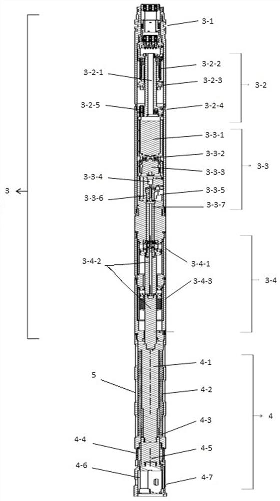
[0048] The first embodiment of the present invention relates to an electro-hydraulic choke fishing tool, such as figure 1 and figure 2As shown, it includes a casing 5. The top of the casing 5 is an upper joint 1 for cables to pass through. The casing 5 is packaged with an electronic sub-section 2, a hydraulic drive sub-section 3 and a self-resetting fishing spear sub-section 4 in sequence from top to bottom. The electronic sub-joint 2 is electrically connected with the hydraulic drive sub-joint 3, and the hydraulic-drive sub-joint 3 pushes the self-resetting fishing spear sub-joint 4 to grab the restrictor through hydraulic oil.
[0049] The working process of the electro-hydraulic choke fishing tool is as follows:
[0050] Inject hydraulic oil into the fishing tool of the electro-hydraulic choke, and the hydraulic oil is filled with the hydraulic drive nipple 3; use the cable to pass through the upper joint 1 and electrically connect the electronic nipple 2, and lower the f...
no. 2 approach
[0054] This embodiment relates to an electro-hydraulic throttling fishing tool, such as figure 1 and figure 2 As shown, it includes a casing 5. The top of the casing 5 is an upper joint 1 for cables to pass through. The casing 5 is packaged with an electronic sub-section 2, a hydraulic drive sub-section 3 and a self-resetting fishing spear sub-section 4 in sequence from top to bottom. The electronic sub-joint 2 is electrically connected with the hydraulic drive sub-joint 3, and the hydraulic-drive sub-joint 3 pushes the self-resetting fishing spear sub-joint 4 to grab the restrictor through hydraulic oil.
[0055] The hydraulic drive nipple 3 includes the connecting joint 3-1, the hydraulic balance mechanism 3-2, the hydraulic power mechanism 3-3 and the driving cylinder mechanism 3-4 from top to bottom, and the lower end of the electronic nipple 2 and the connecting joint 3- 1 Sealed plug connection, the hydraulic balance mechanism 3-2, the hydraulic power mechanism 3-3 and...
no. 3 approach
[0063] This embodiment relates to an electro-hydraulic throttling fishing tool, such as figure 1 and figure 2 As shown, it includes a casing 5. The top of the casing 5 is an upper joint 1 for cables to pass through. The casing 5 is packaged with an electronic sub-section 2, a hydraulic drive sub-section 3 and a self-resetting fishing spear sub-section 4 in sequence from top to bottom. The electronic sub-joint 2 is electrically connected with the hydraulic drive sub-joint 3, and the hydraulic-drive sub-joint 3 pushes the self-resetting fishing spear sub-joint 4 to grab the restrictor through hydraulic oil.
[0064] The hydraulic drive nipple 3 includes the connecting joint 3-1, the hydraulic balance mechanism 3-2, the hydraulic power mechanism 3-3 and the driving cylinder mechanism 3-4 from top to bottom, and the lower end of the electronic nipple 2 and the connecting joint 3- 1 Sealed plug connection, the hydraulic balance mechanism 3-2, the hydraulic power mechanism 3-3 and...
PUM
 Abstract
Description
Claims
Application Information
 - R&D
- Intellectual Property
- Life Sciences
- Materials
- Tech Scout
- Unparalleled Data Quality
- Higher Quality Content
- 60% Fewer Hallucinations
Browse by: Latest US Patents, China's latest patents, Technical Efficacy Thesaurus, Application Domain, Technology Topic, Popular Technical Reports.
© 2025 PatSnap. All rights reserved.Legal|Privacy policy|Modern Slavery Act Transparency Statement|Sitemap|About US| Contact US: help@patsnap.com


