
Hemostatic forceps for gynecology department

A hemostatic forceps and gynecological technology, applied in the field of medical devices, can solve the problems of inability to achieve hemostasis in time, different sizes of bleeding sites, and easily affecting surgical operations, etc., and achieve the effects of convenient surgical operations, accurate drug application sites, and reduced surgical difficulty

Active Publication Date: 2020-10-09
张玉灿
View PDF5 Cites 1 Cited by
  • Summary
  • Abstract
  • Description
  • Claims
  • Application Information

AI Technical Summary

Problems solved by technology

[0004] Although the current hemostatic forceps have many types of jaws to adapt to different surgical occasions, the overall structure of the hemostatic forceps still adopts the traditional scissors structure, which simply clamps blood vessels to achieve hemostasis, and its function is relatively single. Especially in gynecology, pregnant women have bleeding sites of different sizes. The use of existing hemostatic forceps has obvious limitations, and hemostasis cannot be achieved in time. The more bleeding, the more likely it will affect the operation. It is necessary to add some hemostatic drugs to the hemostatic site in time. Therefore, in the process of hemostasis, in addition to holding the hemostatic forceps, the doctor also needs to use other instruments to realize the addition of hemostatic drugs, which increases the difficulty of the operation and brings great inconvenience

Method used


Image

  • Hemostatic forceps for gynecology department
  • Hemostatic forceps for gynecology department
  • Hemostatic forceps for gynecology department

Examples


Embodiment Construction

[0032] In order to enable those skilled in the art to better understand the technical solution of the present invention, the present invention will be described in detail below in conjunction with the accompanying drawings. The description in this part is only exemplary and explanatory, and should not have any limiting effect on the protection scope of the present invention. .

[0033] see Figure 1 to Figure 9 , in a specific embodiment,

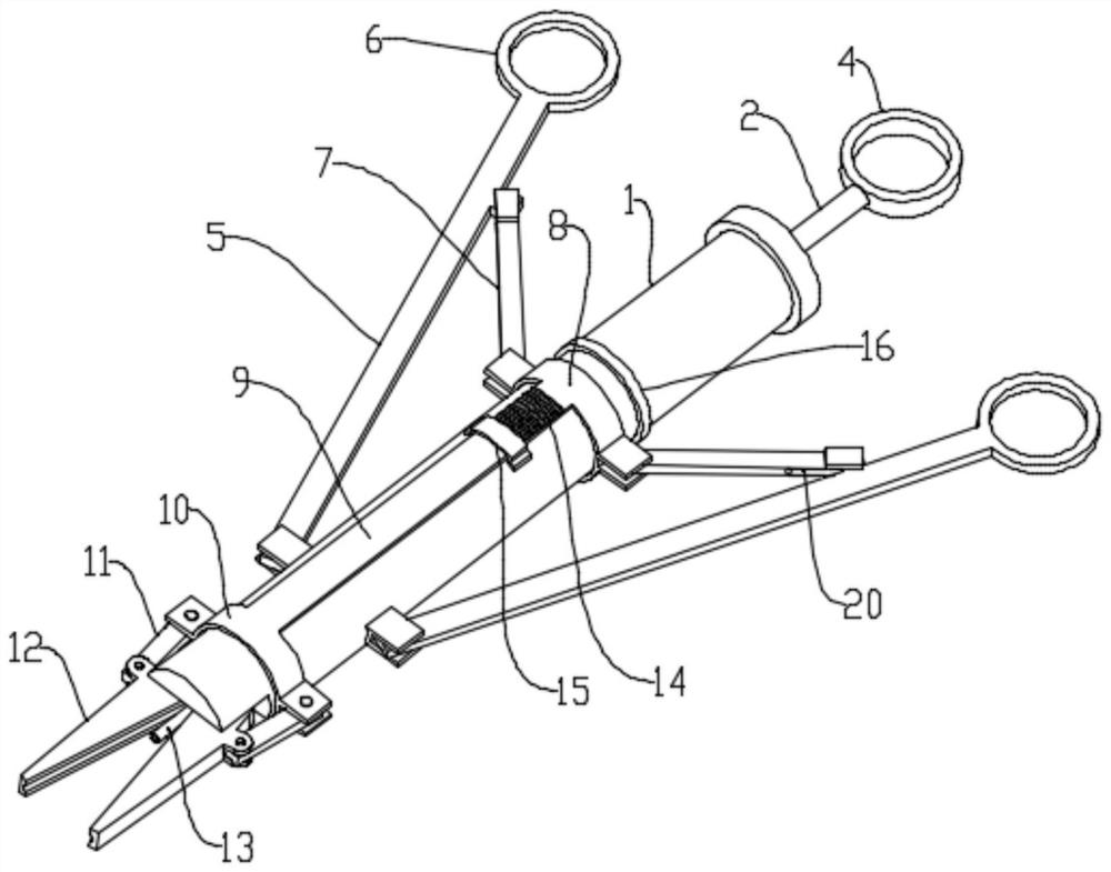
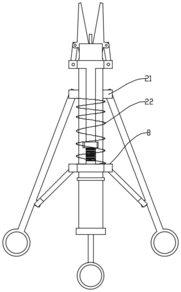
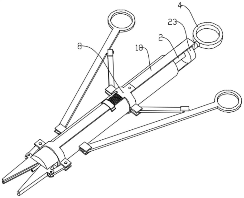
[0034] A gynecological hemostatic forceps, in which operating handles 5 are hinged symmetrically to each other on both sides of a cylinder body 1; a first sliding part 8 and a second sliding part 10 are arranged on the cylinder body 1; the two sides of the first sliding part 8 A movable rod 7 is hinged; the other end of the movable rod 7 is hinged with the operating handle 5; the first slider 8 and the second slider 10 are connected to each other; the cylinder 1 is provided with a piston 3; the piston 3 Connect the piston rod 2; the pisto...


PUM


Abstract

The invention discloses hemostatic forceps for gynecology department, and belongs to the technical field of medical instruments. The operating handles are symmetrically hinged to the two sides of a cylinder body; a first sliding piece and a second sliding piece are arranged on the cylinder body; movable rods are hinged to the two sides of the first sliding piece, the other end of the movable rod is hinged with the operating handle; the first sliding piece and the second sliding piece are connected with each other; a piston is arranged in the cylinder body; the piston is connected with a pistonrod; the piston rod extends out of the tail end of the cylinder body; the front end of the cylinder body is hinged with a jaw which is composed of two clamp parts and can be opened and closed; a movable rod is hinged between the clamp part and the second sliding piece; the front end of the cylinder body is communicated with a needle tube; and the needle tube is positioned between the two clamp parts. The forceps have the main advantages that the forceps can be used for simultaneously conveying medicine to a clamped part according to requirements while clamping hemostasis is realized, assisting the clamped part in hemostasis or treatment or removing redundant blood water, so that the surgical operation of doctors is facilitated, the medicine application part is accurate, the dosage can befreely controlled, great convenience is brought to a gynecological surgery, and the surgical difficulty is reduced.

Description

technical field [0001] The invention belongs to the technical field of medical devices, in particular to a gynecological hemostatic forceps. Background technique [0002] A hemostat is a surgical instrument that clamps blood vessels to block blood. Rescue the patient in the case of bleeding, after taking the hemostatic drug, use the hemostatic forceps to clamp the large artery of the blood vessel to prevent the blood from flowing out. [0003] The principle of use of the hemostat is to clamp blood vessels or fur like clips, but they are sterilized. Hemostatic forceps are divided into large, small, toothed, toothless, straight, and curved. Different types of hemostatic forceps are selected according to different operating parts. [0004] Although the current hemostatic forceps have many types of jaws to adapt to different surgical occasions, the overall structure of the hemostatic forceps still adopts the traditional scissors structure, which simply clamps blood vessels to ...

Claims


Application Information

Patent Timeline
Patent Type & Authority Applications(China)
IPC IPC(8): A61B17/12A61B17/28A61B17/42A61M37/00
CPCA61B17/12A61B17/2804A61B17/42A61B2017/12004A61B2017/2808A61M37/00A61M2205/3379A61M2210/12A61M2210/005
Inventor 王慧楠
Owner 张玉灿
Learn More