
Traction frame for shoulder arthroscopy operation

A technology for shoulder arthroscopy and surgery, applied in the field of medical equipment, can solve problems such as unreliable connection and achieve the effect of reliable connection

Pending Publication Date: 2020-10-09
XIANGYA HOSPITAL CENT SOUTH UNIV
View PDF5 Cites 0 Cited by
  • Summary
  • Abstract
  • Description
  • Claims
  • Application Information

AI Technical Summary

Problems solved by technology

[0006] Aiming at the deficiencies of the prior art, the present invention provides a traction frame for shoulder arthroscopy, which solves the problem of unreliable connection between the body and the base of the traction frame for shoulder arthroscopy provided in the above patent documents

Method used


Image

  • Traction frame for shoulder arthroscopy operation
  • Traction frame for shoulder arthroscopy operation
  • Traction frame for shoulder arthroscopy operation

Examples


Embodiment 1

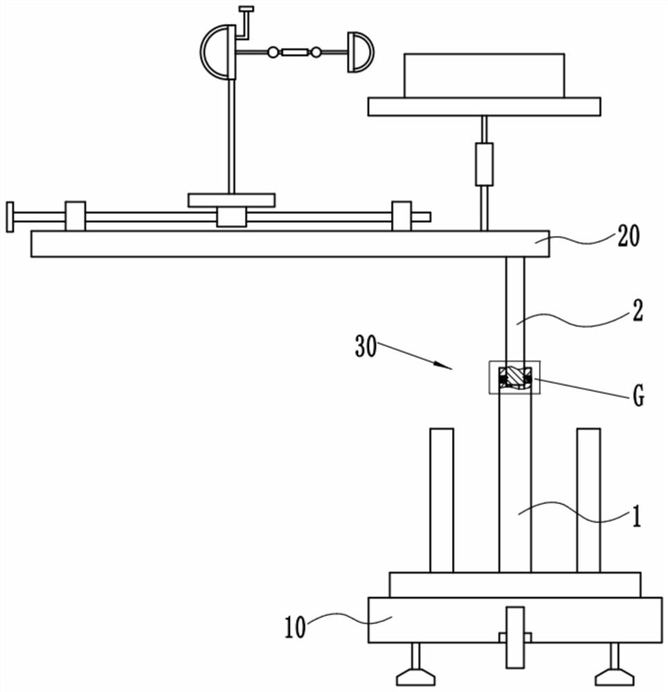
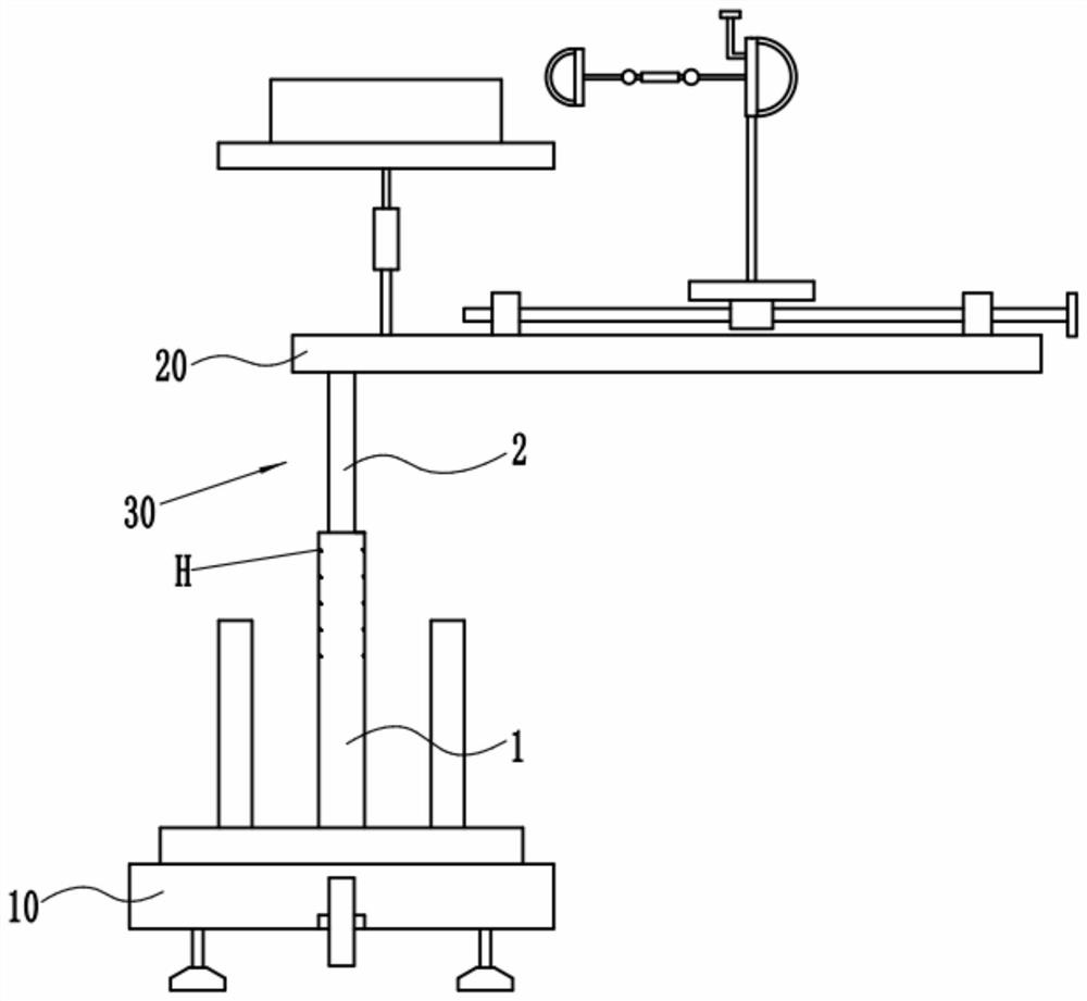
[0040] Such as figure 1 and figure 2 The shown traction frame for shoulder arthroscopic surgery includes a base and a frame body, the base includes a bottom plate 10, the frame body includes a supporting plate 20, and a telescopic rod 30 is passed between the bottom plate 10 and the supporting plate 20 connected, the telescopic rod 30 includes a fixed sleeve 1 connected to the bottom plate 10 and a moving rod 2 arranged at the lower end of the supporting plate 20, the moving rod 2 is slidably matched with the fixed sleeve 1, and the Both sides of the fixed sleeve 1 are respectively provided with several connecting components, and the moving rod 2 can be connected with the fixed sleeve 1 through a corresponding pair of connecting components, so that the connection between the moving rod 2 and the fixed sleeve 1 can be Reliable connection between them, so that the supporting plate 20 can be reliably connected with the bottom plate 10, and then the frame body can be reliably co...

Embodiment 2

[0050] Such as Figure 6 As shown, on the basis of the first embodiment, the engaging assembly further includes an engaging member 7 arranged on the side wall of the installation hole 21, and the engaging member 7 includes a An annular plate 71, the inner end of the annular plate 71 is provided with an elastic cone 72, the large end of the elastic cone 72 is connected with the inner end of the annular plate 71, and the inner wall of the elastic cone 72 Several annular rubber plates 73 are provided, and an O-shaped rubber ring 74 is arranged on the inner circumference of the annular rubber plate 73, and the O-shaped rubber ring 74 can correspond to the outer circumference of the base rod 53 of the connecting rod 5. The annular groove 531 is snap-connected so as to securely connect the moving rod 2 to the fixed sleeve 1 .

[0051] In this embodiment, the elastic cone 72 is made of rubber.

Embodiment 3

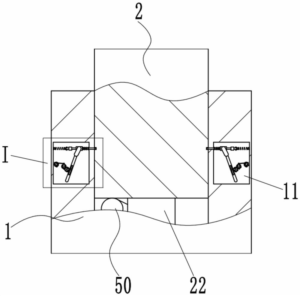
[0053] Such as image 3 and Figure 7 As shown, a first spring 50 is provided between the bottom end of the moving rod 2 and the bottom wall of the inner cavity of the fixed sleeve 1, and one end of the first spring 50 is sleeved on the moving rod 2. On the upper guide column 22 at the bottom end, the other end of the first spring 50 is sleeved on the lower guide column 12 on the bottom wall of the inner cavity of the fixed sleeve 1. Due to the setting of the first spring 50, the telescopic The structure of the rod 30 is more stable.


PUM


Abstract

The invention discloses a traction frame for a shoulder arthroscopy operation. The traction frame comprises a bottom plate and a bearing plate, the bottom plate is connected with the bearing plate through a telescopic rod, the telescopic rod comprises a fixed sleeve connected with the bottom plate and a movable rod arranged at the lower end of the bearing plate, the movable rod is in sliding fit with the fixed sleeve, a plurality of connecting assemblies are arranged on the two sides of the fixed sleeve respectively, and the movable rod can be connected with the fixed sleeve through a pair ofcorresponding connecting assemblies. According to the traction frame for the shoulder arthroscopy operation, due to the fact that the structure is adopted, a frame body and a base can be reliably connected, operation of medical staff is facilitated, and a patient can be treated conveniently.

Description

technical field [0001] The invention relates to a medical device, in particular to a traction frame for shoulder arthroscopic surgery. Background technique [0002] Shoulder arthroscopic surgery is suitable for joint loose body, biceps rupture, osteoarthritis and other surgical treatments. [0003] Chinese patent CN201810802662.9 discloses a traction frame for shoulder arthroscopic surgery, which includes a base and a body matched with the base. Connecting holes, the frame body includes a plug-in tube, and the tube body of the plug-in tube has several plug-in threaded holes from top to bottom. The frame body is fixedly connected with the base, the frame body includes a supporting plate, and the supporting plate is connected with the upper end of the insertion pipe, and the supporting plate has a traction member. [0004] The above-mentioned patent documents have a socket and a socket, and the socket and the socket are connected by bolts and threads, and through the coopera...

Claims


Application Information

Patent Timeline
Patent Type & Authority Applications(China)
IPC IPC(8): A61B90/14A61G13/12
CPCA61B90/14A61G13/1235A61G13/126A61G2210/10
Inventor 李宇晟谢文清肖文峰雷光华禹登杰何苗杨韫韬柳笛蔡梓俊
Owner XIANGYA HOSPITAL CENT SOUTH UNIV
Learn More