Rotating disc type automatic punching machine
A punching machine and rotary table technology, applied in the field of rotary table automatic punching machines, can solve the problems of long interval time, reduced production efficiency, difficult finished product, etc., to shorten the interval time, improve production efficiency, and facilitate the collection of finished products.
- Summary
- Abstract
- Description
- Claims
- Application Information
AI Technical Summary
Problems solved by technology
Method used
Image


Examples
Embodiment 1
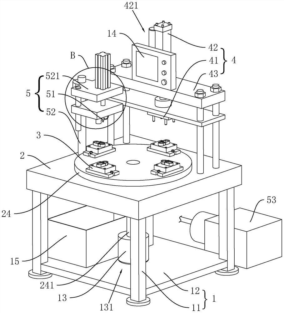
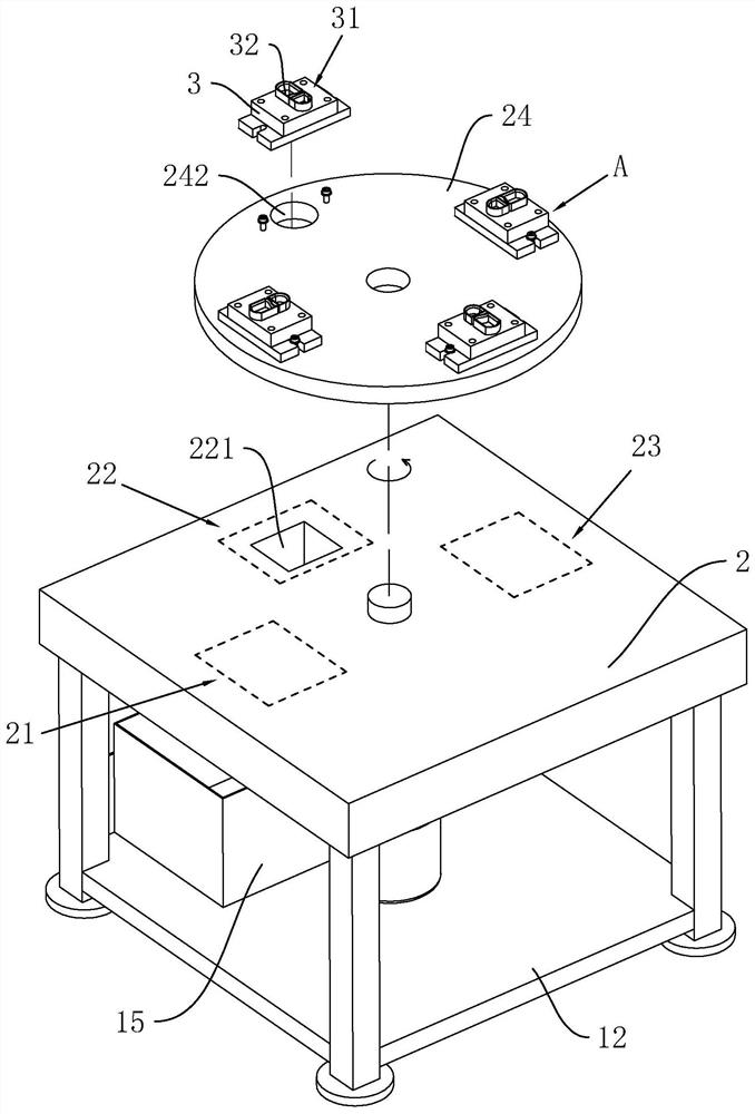
[0040] The embodiment of the present application discloses a rotary table 24-type automatic punching machine, which can realize automatic material receiving during the working process, is convenient for users to operate, and improves production efficiency. refer to figure 1 , The turntable automatic stamping machine includes a frame 1, a workbench 2 arranged on the frame 1, a loading mechanism arranged on the workbench 2 and a stamping mechanism 4 arranged on the upper surface of the workbench 2. The loading mechanism includes a turntable 24 hinged on the upper surface of the worktable 2 and multiple groups of molds 3 distributed on the upper surface of the turntable 24 in a circumferential manner. A discharge mechanism 5 is also provided on the workbench 2, and a collection tray 15 for collecting finished products is provided in the frame 1 . In the working state, the turntable 24 drives each mold 3 to pass through the stamping mechanism 4 and the discharge mechanism 5 in tu...
Embodiment 2
[0052] refer to Figure 4 and Figure 5The difference between this embodiment and Embodiment 1 is that the lifting block 54 is provided with a swing assembly 6 that can drive the air nozzle 51 to swing. When the lifting block 54 is lifted, the air nozzle 51 sprays air to multiple positions by swinging. The lift block 54 is provided with a drive shaft 61 for the air nozzle 51 to be hinged, and the drive shaft 61 is located directly below the support block 521 . The driving shaft 61 passes through the lifting block 54 in a vertical direction and is rotatably connected with the lifting block 54 . An eccentric rod 62 is welded to the end of the driving shaft 61 close to the lifting block 54, and the angle between the eccentric rod 62 and the driving shaft 61 is 90°. One end of the air nozzle 51 close to the eccentric rod 62 is welded with a swing rod 511 , and the swing rod 511 is coaxially connected with the air nozzle 51 . An end of the swing rod 511 close to the eccentric ro...
PUM
 Abstract
Description
Claims
Application Information
 - Generate Ideas
- Intellectual Property
- Life Sciences
- Materials
- Tech Scout
- Unparalleled Data Quality
- Higher Quality Content
- 60% Fewer Hallucinations
Browse by: Latest US Patents, China's latest patents, Technical Efficacy Thesaurus, Application Domain, Technology Topic, Popular Technical Reports.
© 2025 PatSnap. All rights reserved.Legal|Privacy policy|Modern Slavery Act Transparency Statement|Sitemap|About US| Contact US: help@patsnap.com