
A precision grinding method for gt35 motor shaft

A grinding method and technology for motor shafts, which are applied to grinding drive devices, grinding workpiece supports, grinding machine parts, etc., can solve problems such as inability to guarantee cylindricity requirements, affecting the working performance of motor shafts, and peeling titanium carbide particles. , to achieve the effect of eliminating appearance defects, good embedding function and long service life

Active Publication Date: 2021-12-07
BEIJING INST OF AEROSPACE CONTROL DEVICES
View PDF7 Cites 0 Cited by
  • Summary
  • Abstract
  • Description
  • Claims
  • Application Information

AI Technical Summary

Problems solved by technology

[0003] On the one hand, the existing processing method cannot guarantee the cylindricity requirements, and the shaft is deformed such as waist drum shape and edge collapse, which affects the improvement of cylindricity; on the other hand, the abrasive grains during the grinding process will scratch the surface, and the titanium carbide particles It will also partly peel off, forming microscopic holes or groove structures, which will affect the working performance of the motor shaft

Method used


Image

  • A precision grinding method for gt35 motor shaft
  • A precision grinding method for gt35 motor shaft
  • A precision grinding method for gt35 motor shaft

Examples


Embodiment 1

[0061] Adopt the precision grinding method of GT35 motor shaft in the present invention to grind the GT35 motor shaft on the air-floating pressure motor, the specific steps and requirements are as follows:

[0062] (1) The outer circle of the motor shaft is first ground by the method of cylindrical grinding;

[0063] (1.1) The shaft is clamped by the double center;

[0064] (1.2) Use a 600-mesh diamond grinding wheel to grind the motor shaft, and the back cutting amount is not more than 0.01mm;

[0065] (1.3) Grinding multiple times, the cumulative grinding amount is not less than 0.2mm;

[0066] (1.4) Thin slice grinding wheel is used, and the grinding speed of the grinding wheel is 30m / s;

[0067] (1.5) The feed speed of the grinding wheel is 100mm / min, and each time a shaft is ground, it is trimmed once with a diamond pen;

[0068] (1.6) 10 times microscope inspection after grinding, no visible scratches on the surface, no hard phase peeling off.

[0069] (2) The shaft ...


PUM

PropertyMeasurementUnit
thicknessaaaaaaaaaa
Cylindricityaaaaaaaaaa

Abstract

The invention provides a precision grinding method for a GT35 motor shaft, which grinds the outer circle of the motor shaft to achieve a cylindricity of 2 μm or less and a surface roughness of Ra0.1 or less; the motor shaft after grinding is cleaned with ultrasonic waves and cleaning media After cleaning, filter the cleaning medium with filter paper until there are no sand particles; fix the motor shaft on the main shaft of the machine tool, the main shaft of the machine tool is coaxial with the motor shaft, set the grinding tool on the motor shaft and lock it; set as required The main shaft of the machine tool rotates at a high speed and starts to rotate. The hand-held fixture reciprocates on the motor shaft. The abrasive sand with a particle size of W5 is used for rough grinding, the abrasive sand with a particle size of W3 is used for semi-finishing, and the abrasive sand with a particle size of W1 is used for finishing. motor shaft. The grinding method in the present invention makes the cylindricity of the GT35 motor shaft better than 0.3 μm, and the surface roughness is better than Ra0.025, and there is no hard phase peeling and damage on the surface, and no scratches on the surface, which significantly improves the GT35 shaft parts. Precision.

Description

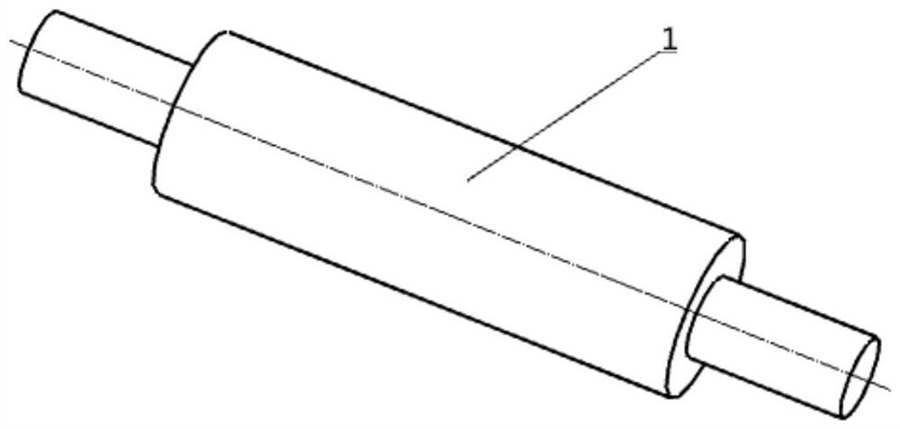
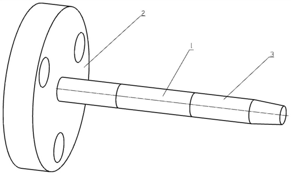
technical field [0001] The invention relates to a machining method for the outer circle of a precision small shaft made of GT35 material, in particular to a precision grinding method for a GT35 motor shaft, and belongs to the technical field of precision machining. Background technique [0002] GT35 material belongs to steel-bonded hard alloy. Adding 35% titanium carbide particles in the matrix of chrome-molybdenum alloy steel, the material has high wear resistance and high hardness. The quenching hardness reaches HRA86 or above, and is especially suitable for making dynamic pressure motor shafts. Such as figure 1 with figure 2 As shown, the outer circle of the dynamic pressure motor shaft is the working surface, and the cylindricity requirements are extremely high, and the cylindricity needs to be below 0.3 μm. [0003] On the one hand, the existing processing method cannot guarantee the cylindricity requirements, and the shaft is deformed such as waist drum shape and ed...

Claims


Application Information

Patent Timeline
Patent Type & Authority Patents(China)
IPC IPC(8): B24B1/00B24B41/06B24B47/12B24B49/00B24B47/20
CPCB24B1/00B24B41/062B24B47/12B24B47/20B24B49/006
Inventor 张纱李峰刘德亮张勇甄立穆文海王永
Owner BEIJING INST OF AEROSPACE CONTROL DEVICES
Learn More