Robot precise joint speed reducer

A joint reducer and robot technology, applied in the field of robots, can solve the problems of rigid gear wear, large gyration clearance, unfavorable output precision control, etc., and achieve the effect of improving service life and processing accuracy

Inactive Publication Date: 2020-10-09
WEIFANG UNIVERSITY
View PDF10 Cites 4 Cited by
  • Summary
  • Abstract
  • Description
  • Claims
  • Application Information

AI Technical Summary

Problems solved by technology

[0003] The reducer mainly adopts rigid input and rigid output, such as RV reducer, which adopts rigid input and rigid output, and the power on the input shaft is transmitted to the output shaft through rigid gears. This will cause a large transmission error when the rigid gear meshes with the output shaft, which is not conducive to the control of output accuracy, and after the gear reducer has been working for a long time, the wear will become greater and greater, and the gyration clearance will also increase. ;Because it uses rigid gears to mesh with the output shaft, it requires high machining accuracy for rigid gears, making the processing of rigid gears more difficult
[0005] (1) The rigid gear will be worn during the transmission process, which will cause a large transmission error when the rigid gear meshes with the output shaft, which is not conducive to the control of output accuracy, and after the gear reducer has been working for a long time, the wear will become more and more serious. The larger the gyration clearance will be, the larger it will be;
[0006] (2) Since the rigid gear meshes with the output shaft, the machining accuracy of the rigid gear is required to be high, which makes the processing of the rigid gear more difficult

Method used


Image

  • Robot precise joint speed reducer
  • Robot precise joint speed reducer
  • Robot precise joint speed reducer

Examples


Embodiment Construction

[0064] In order to make the object, technical solution and advantages of the present invention more clear, the present invention will be further described in detail below in conjunction with the examples. It should be understood that the specific embodiments described here are only used to explain the present invention, not to limit the present invention.

[0065] Aiming at the problems existing in the prior art, the present invention provides a precision joint reducer for robots. The present invention will be described in detail below with reference to the accompanying drawings.

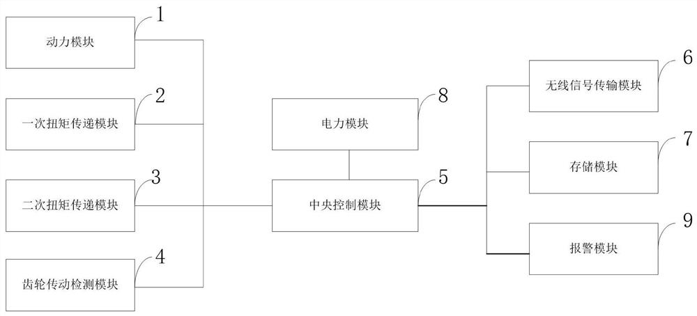
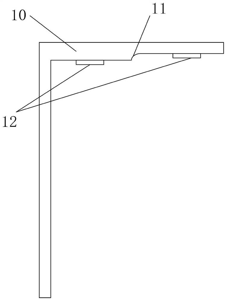
[0066] like figure 1 and figure 2 As shown, the structure of the robot precision joint reducer provided by the present invention specifically includes:

[0067] The power module 1 is connected to the central control module 5 and includes a power wheel, which is used to drive the power wheel to rotate through the motor;

[0068] The primary torque transmission module 2 is connected with the centr...


PUM


Abstract

The invention belongs to the technical field of robots, and discloses a robot precise joint speed reducer. The robot precise joint speed reducer comprises a power module, a primary torque transmissionmodule, a secondary torque transmission module, a gear transmission detection module, a central control module, a wireless signal transmission module, a storage module, an electric power module and an alarm module. According to the robot precise joint speed reducer, the front surface and the back surface of an eccentric gear assembly are engaged with the contact print through a collection micro camera, the collected contact print image is denoised through an image processing unit, the collected front surface and the back surface of the eccentric gear assembly are engaged with the contact print through an image measurement unit to be measured and recorded, the processing result is compared and analyzed with a preset threshold value, so that the transmission error and the abrasion state ofmeshing of a rigid gear and an output shaft can be found in time, precision control is facilitated, and by means of the machining method of the eccentric gear assembly, the machining precision of therigid gear can be improved, and the service life is prolonged.

Description

technical field [0001] The invention belongs to the technical field of robots, and in particular relates to a robot precision joint reducer. Background technique [0002] At present, with the development of science and technology and industry, robots have attracted more and more attention due to their powerful functions, and have gradually developed from the industrial production industry to replace many positions in people's lives. The main service functions of the robot are realized by the transformation activities of the joint parts of the robot, and the joint position and core components of the robot are reducers; [0003] The reducer mainly adopts rigid input and rigid output, such as RV reducer, which adopts rigid input and rigid output, and the power on the input shaft is transmitted to the output shaft through rigid gears. This will cause a large transmission error when the rigid gear meshes with the output shaft, which is not conducive to the control of output accu...

Claims


Application Information

Patent Timeline
Patent Type & Authority Applications(China)
IPC IPC(8): B25J9/10B25J9/16B25J17/00F16H7/02F16H7/08B23P15/14
CPCB23P15/14B25J9/10B25J9/102B25J9/16B25J17/00F16H7/02F16H7/08
Inventor 张丽娜鲍文科解福祥
Owner WEIFANG UNIVERSITY
Why Eureka
Try Eureka