
Pressure regulating type relay valve

A relay valve and pressure regulating technology, which is applied in the field of auto parts, can solve the problems such as the difficult realization of the valve structure, achieve reasonable structure, solve the brake weakness, and optimize the obvious effect

Pending Publication Date: 2020-10-09
RUILI GROUP RUIAN AUTO PARTS CO LTD
View PDF2 Cites 0 Cited by
  • Summary
  • Abstract
  • Description
  • Claims
  • Application Information

AI Technical Summary

Problems solved by technology

The above-mentioned emergency relay valve adjusts the air pressure at the output port by setting a pressure regulating device to achieve different braking requirements. However, the structure, position and connection relationship of the pressure regulating device and the principle of the pressure regulating device in the above patent documents It is not ideal, making it difficult for those skilled in the art to realize when setting the pressure regulating device or using the pressure regulating device to form a new valve structure

Method used


Image

  • Pressure regulating type relay valve
  • Pressure regulating type relay valve
  • Pressure regulating type relay valve

Examples


Embodiment 1

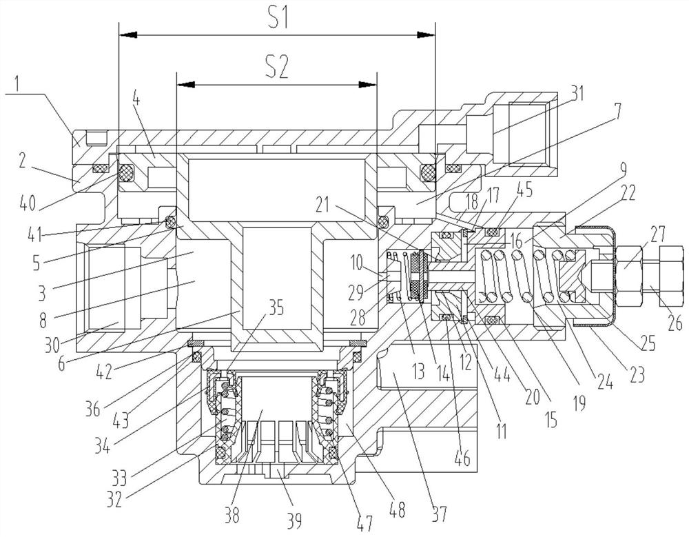
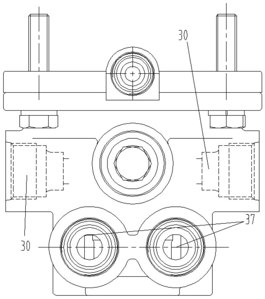
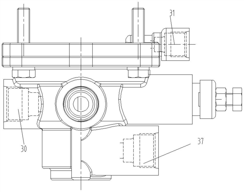
[0031] This embodiment discloses a pressure-regulating relay valve, which includes a casing, the casing includes an upper casing 1 and a lower casing 2 that cooperate with each other, and a relay cavity 3 is formed in the casing, and a relay cavity 3 is formed in the casing. A relay piston capable of reciprocating movement is arranged in the cavity 3, and the relay piston is divided into three sections, which are a pressure application section 4, a pressure regulation section 5 and a control section 6. The pressure application section 4, the pressure regulation section A first pressure regulating chamber 7 is formed between the section 5 and the relay cavity 3, a control chamber 8 is formed around the control section 6, and a control section capable of being controlled by the relay piston is arranged below the relay piston. 6 operating intake and exhaust structures; also includes a pressure regulating structure, the pressure regulating structure communicates with the first pres...


PUM


Abstract

The invention discloses a pressure regulating type relay valve. A relay piston is divided into three sections; a first pressure regulating cavity and a control cavity are formed; a pressure regulatingstructure is arranged between the first pressure regulating cavity and the control cavity; when a brake pedal is stepped down, the air pressure of the brake main valve enters through a control inletto push the relay piston to move; through pressure change of gas entering the control cavity and the first pressure regulating cavity by the pressure regulating structure, output of pressure in the control cavity is realized, and output of different brake pressures by a brake air chamber is realized, so that the functions of gently treading and heavily treading and heavily braking are realized, and the problem of fatigue and weakness of brakes of large heavy trucks and other vehicles in the domestic market is solved.

Description

technical field [0001] The invention relates to the technical field of auto parts, in particular to a pressure regulating relay valve. Background technique [0002] The relay valve is a part of the automobile air brake braking system, its air inlet is connected to the air storage tank, and the air outlet is connected to the brake chamber. When the brake pedal is stepped on, the output air pressure of the brake valve is used as the control pressure input of the relay valve. Under the action of the control pressure, the air intake valve is pushed open, so the compressed air enters the brake directly from the air storage tank through the air inlet. The dynamic air chamber does not need to flow through the brake valve, which greatly shortens the charging line of the brake air chamber and accelerates the restart process of the air chamber. For example, Chinese patent document CN102481919A discloses a relay valve device, which has a housing, a longitudinally movable relay piston ...

Claims


Application Information

Patent Timeline
Patent Type & Authority Applications(China)
IPC IPC(8): B60T15/18B60T13/26
CPCB60T13/26B60T15/18
Inventor 徐磊傅瑛吴慧敏高炳爃
Owner RUILI GROUP RUIAN AUTO PARTS CO LTD
Learn More