Self-learning rotational speed control method based on active observation of load change rate
What is AI technical title?
AI technical title is built by Patsnap AI team. It summarizes the technical point description of the patent document.
A load change and control method technology, applied in engine control, electrical control, fuel injection control, etc., can solve problems such as poor speed control quality, achieve the effects of improving robustness, reducing calibration workload, and improving control quality
Active Publication Date: 2020-10-09
TIANJIN UNIV
View PDF6 Cites 3 Cited by
Summary
Abstract
Description
Claims
Application Information
AI Technical Summary
This helps you quickly interpret patents by identifying the three key elements:
Problems solved by technology
Method used
Benefits of technology
Problems solved by technology
[0005] The purpose of the present invention is to provide a self-learning speed control method based on the active observation of the load change rate in order to solve the problem of poor speed control quality caused by unknown load torque in the engine speed control existing in the prior art
Method used
Image
Click on the blue label to locate the original text in one second.
Reading with bidirectional positioning of images and text.
Examples
Embodiment 1
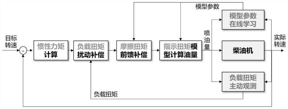
[0045] A method for self-learning control of engine speed based on active observation of load change rate, comprising the following steps:
[0046] Step 1, according to the deviation between the target engine speed and the actual engine speed, calculate the required moment of inertia through feedback control; use the friction torque model to estimate the current friction torque to obtain the friction torque;
[0047] Step 2, aiming at the dynamic change process of the engine speed, on the basis of the dynamic speed, add two "expansion states" of load torque and load torque change rate;
[0048] Step 3, using the reduced-order extended state observer method, combined with the friction torque, to observe the rotational speed, load torque and load torque change rate online, and obtain an estimated value of the load torque;
[0049] Step 4, on the basis of the moment of inertia obtained in step 1, use the estimated value of the load torque observed in step 3 to make compensation t...
Embodiment 2
[0056] Further, in the step 1, the moment of inertia u 0 The calculation method is:
[0057] u 0 =k p (ω ref -ω) (1)
[0058] where: ω ref is the target engine speed (unit: rpm), ω is the actual engine speed (unit: rpm), the engine can be a diesel engine, k p It is a proportional coefficient, which can be adjusted according to the required speed response speed.
[0059] Furthermore, in the step 2, the differential equation model of the engine speed adds two "expansion states" to obtain a speed dynamic model with expansion states:
[0060] Rewritten as formula (2):
[0061]
[0062] Among them, ω is the actual speed of the engine (unit: rpm), Represents the derivative of the actual engine speed, J is the moment of inertia of the crankshaftrotation system (unit: kg m 2 ), M i is the indicated torque (unit: Nm), M Fri is the friction torque (unit: Nm), M load is the load torque (unit: Nm).
[0063] To simplify the expression of (2), let As the equivalent l...
PUM
Abstract
The invention discloses a self-learning rotational speed control method based on active observation of a load change rate. The method comprises the following steps of step 1, computing a rotational inertia moment through feedback control, and estimating current friction torque by using a friction torque model to obtain friction torque; step 2, increasing two expanded states, namely load torque anda load torque rate based on dynamic changes in rotational speed of an engine; step 3, performing on-line iteration through an observer, and performing on-line detection on the rotational speed, the load torque and the load torque change rate; step 4, compensating by utilizing an estimated value of the load torque based on the rotational inertia moment in order to obtain effective torque, and superposing the friction torque in the step 1 based on the effective torque in order to obtain indication torque; and step 5, obtaining oil injection quantity by calculation through an indication torque model of the engine, and enabling an oil injection control system to control the rotational speed according to the oil injection quantity. According to the method, the reasons for fluctuation of the engine are solved, and the anti-interference capability of rotational speed control is remarkably improved.
Description
technical field [0001] The invention relates to the technical field of engine speed control, in particular to a self-learning speed control method based on active observation of load change rate. Background technique [0002] Speed control is one of the important functions of engine control. The quality of speed control has a significant impact on the fuel consumption and comfort of the engine at idle speed, the stability of the voltage and power of the generator for power generation, and the smoothness of the mode transition in the hybridsystem. Although engine speed control is not a new problem, the problem of unknown load torque has not been well solved, which also affects the quality of speed control. [0003] Proportional-derivative-integral (PID) control is the most commonly used speed control algorithm. At that time, in order to ensure the control quality, complex parameter calibration was usually required. Robust control is a controller with relatively stable pe...
Claims
Application Information
Patent Timeline
Application Date:The date an application was filed.
Publication Date:The date a patent or application was officially published.
First Publication Date:The earliest publication date of a patent with the same application number.
Issue Date:Publication date of the patent grant document.
PCT Entry Date:The Entry date of PCT National Phase.
Estimated Expiry Date:The statutory expiry date of a patent right according to the Patent Law, and it is the longest term of protection that the patent right can achieve without the termination of the patent right due to other reasons(Term extension factor has been taken into account ).
Invalid Date:Actual expiry date is based on effective date or publication date of legal transaction data of invalid patent.

