Bridge floor roughness identification method based on two-connected measurement vehicle vibration signals

An identification method and vibration signal technology, applied in measuring devices, instruments, using ultrasonic/sonic/infrasonic waves, etc., can solve the problems of universal measurement, high-cost operation technology, and difficulty in effectively solving the huge demand of road bridges, etc. question

Active Publication Date: 2020-10-09
CHONGQING UNIV
View PDF5 Cites 4 Cited by
  • Summary
  • Abstract
  • Description
  • Claims
  • Application Information

AI Technical Summary

Problems solved by technology

However, the direct measurement method has the following problems: (1) Subjective inspection based on vision has strong subjectivity, and depends to a large extent on the experience level of the inspector; (2) Measurement with the help of measuring equipment The method usually involves a lot of measurement equipment, such as laser p

Method used


Image

  • Bridge floor roughness identification method based on two-connected measurement vehicle vibration signals
  • Bridge floor roughness identification method based on two-connected measurement vehicle vibration signals
  • Bridge floor roughness identification method based on two-connected measurement vehicle vibration signals

Examples


Embodiment 1

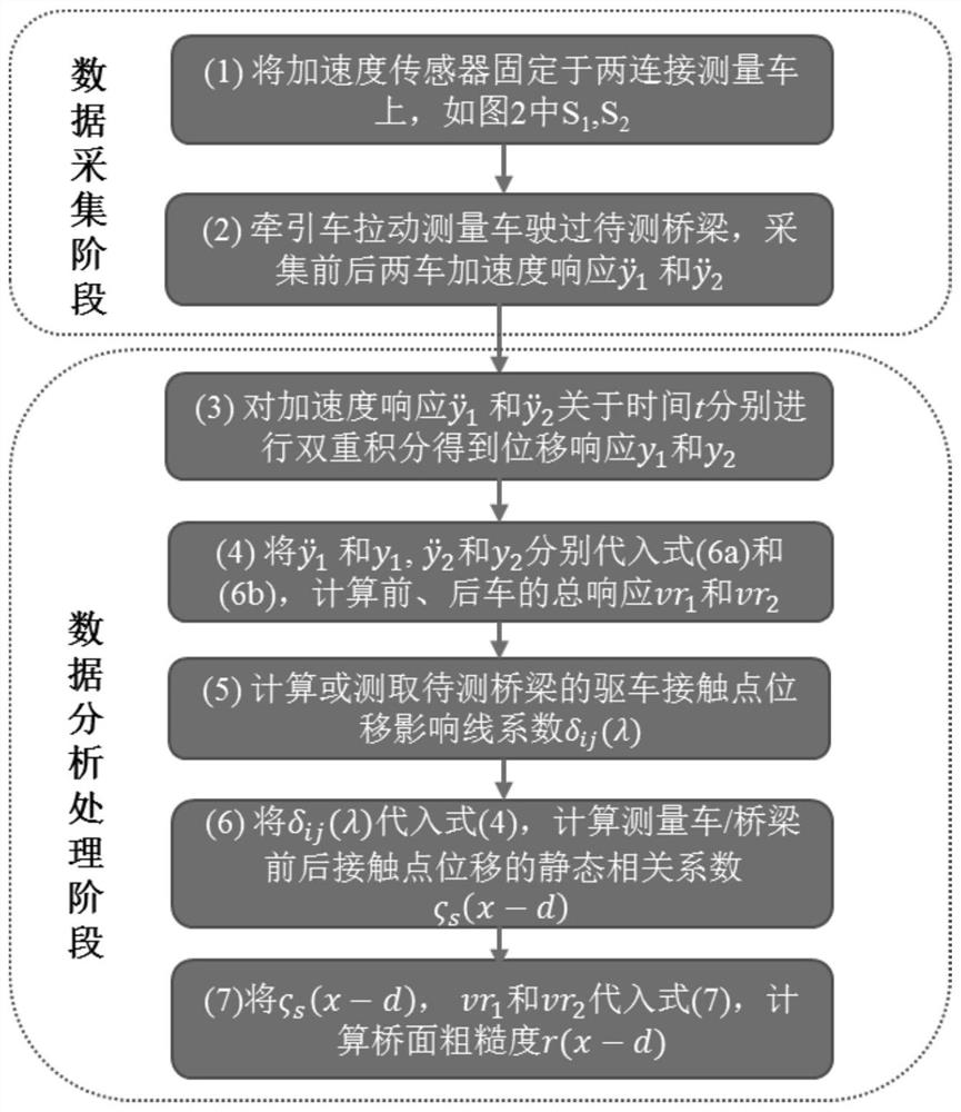
[0046] A method for identifying the roughness of a bridge deck based on the vibration signal of a two-connection measuring vehicle, which is characterized in that it comprises the following steps:

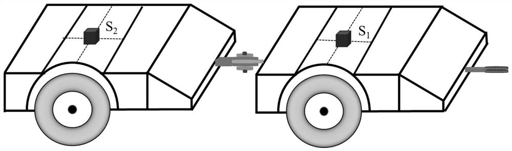
[0047] (1) Install two acceleration sensors connected to the measuring vehicle system: set the acceleration sensor S 1 , S 2 They are respectively fixed to the position of the carriage directly above the center of the front and rear wheel axles (or respectively fixed to the center positions of the front and rear wheel axles), see attached figure 2 ;

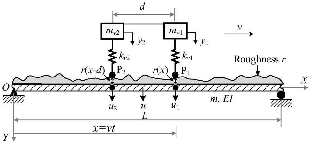
[0048] (2) The tractor equipment provides system power to pull the two connected measuring vehicle systems to drive across the bridge under test at a constant speed, and the signal acquisition system separately collects the vertical acceleration response of the front and rear single-axle vehicles included in the measuring vehicle system during the bridge crossing process. versus The dynamic balance equation of the front and rear two cars ...


PUM


Abstract

The invention provides a bridge floor roughness identification method based on two-connected measurement vehicle contact point displacement influence lines. According to the strategy of the method, vertical displacement of a bridge is eliminated from vehicle response, so that pure road surface roughness information is obtained, and precise identification of the bridge surface roughness is achieved. The core thought is as follows: based on an influence line principle and the space position relationship of front and rear vehicles, an approximate correlation relationship (defined as a static correlation coefficient) of bridge vertical displacement u1(x-d) and u2(x-d) at a contact point of the front vehicle and the rear vehicle is established, and an additional constraint condition can be provided for decoupling of the bridge vertical displacement and the bridge floor roughness, so that the bridge vertical displacement is eliminated from responses of the front vehicle and the rear vehicle,and the purpose of precisely identifying the road surface roughness is achieved. The method can replace traditional and expensive instruments and equipment, realizes rapid detection of bridge pavement conditions, and effectively avoids traffic jam caused by road closure operation.

Description

Technical field [0001] The invention belongs to the technical field of bridge maintenance and management, and specifically relates to a method for identifying the roughness of a bridge deck based on a displacement influence line of a contact point of a two-connection measuring vehicle system. Background technique [0002] The road surface roughness is the deviation of the bridge surface relative to the ideal smooth plane, and it is the decisive factor affecting the coupled vibration of the vehicle-bridge system. On the one hand, it will act on the vehicles on the bridge to produce vibration response, especially vertical vibration, which affects the smoothness and safety of vehicle operation; on the other hand, the agitated vehicle vibration will react on the bridge and enlarge the bridge. Structural dynamic effects. As the service time increases, the traffic load becomes denser, overloads occur frequently, and environmental erosion and other unfavorable conditions accumulate, th...

Claims


Application Information

Patent Timeline
IPC IPC(8): G01B17/08G01N19/00
CPCG01B17/08G01N19/00
Inventor 杨永斌王志鲁王保全
Owner CHONGQING UNIV
Why Eureka
Try Eureka